Brake system Ural 4320
The topic of the article presented today will be the Ural 4320 brake system. In the presented article, you can find both a description of the system itself, namely its equipment and features, as well as its main breakdowns and methods for solving them.
The topic of the article presented today will be the brake system of the Ural 4320 car. The main task of the brake system is to control the speed of the car, stop it, and also keep it in one location using the force that occurs between the road and the wheels of the car when it stops. In this article, we will answer the following questions:
- What is the braking system of a Ural 4320 car?
- How does the braking system work?
- How many brake systems are installed on a car brand?
- How does the braking system work?
- The main malfunctions of the brake system Ural 4320;
- What can cause various malfunctions of the brake system of a car?
- Diagnostics of the brake system Ural 4320 at the stand;
- How is the braking mechanism adjusted?
- Replacing the brake fluid on a car brand Ural 4320.
The braking system provides a change in the speed of movement of cars, which occurs at the signal of the car owner or electric management. The second purpose is to save the vehicle in a stationary state in relation to the road surface, during a stop.
The braking force is generated by the machine engine, the mechanism for braking the wheels of the machine, the electronic or hydraulic retarding brake located in the transmission. To ensure the functioning of all the previously listed functions, three types of brake systems are installed on Ural 4320 cars.
Consequently, the question arises, what kind of braking systems are installed on cars of the URAL 4320 brand?
- Working brake system. This system is used at all speeds of the Ural 4320 without exception to stop or reduce speed. And it starts to work almost simultaneously with pressing the brake. This type is almost the most effective in comparison with others.
- Parking brake system. It is necessary to keep the vehicle in place for a certain period of time. It is thanks to her that the possibility of moving the car without the command of the owner of the car is excluded.
- Auxiliary brake system. The auxiliary type is used on machines with a large weight to stop on various slopes. Very often it happens that the functioning of this system is ensured by the machine engine, on which the pipeline is closed with a damper.
Also, cars are equipped with an emergency brake release system for parking brakes, a trailer brake drive, an alarm on the functioning of the braking system and a control system. A spare brake system can also be installed, which is used when the main unit is faulty. This type of braking unit can be of 2 types, autonomous or partially functioning due to the working system.
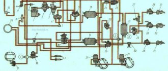
The braking system of the Ural 4320 car is equipped with the following mechanisms and devices:
- Brake mechanism;
- Brake valve;
- Pneumatic cylinders;
- Automatic brake force regulator;
- receivers;
- pressure gauge;
- Sensors;
- valves;
- Compressor;
- Adjusting lever;
- Moisture distributor;
- Pressure regulator;
- Pneumatic pipeline;
- trailer crane;
- Four-circuit safety valve;
- The mechanism of the auxiliary braking system.
The principle of operation of the braking mechanism
Let's look at the principle of operation of the Ural 4320 braking system. When you press the brake pedal, the load will transfer to the amplifier, which creates additional resistance on the main cylinder. The piston of such a cylinder drives all the liquid in the cylinders of the machine wheels with the help of pipelines. Moreover, simultaneously with this process, the pressure of the drive fluid increases. With the help of pistons in the cylinders of machine wheels, the brake pads move to the disks, or drums.
When the brake pedal is pressed, the fluid pressure increases, which means that the stopping mechanisms are activated, which slow down the rotation of the machine wheels and generate braking forces in those places where the machine contacts the road surface. Moreover, the more force is applied to the pedal, the more efficiently and quickly the car wheels will stop. The liquid pressure at the moment of stopping can reach from ten to fifteen megapascals.
At the end of the stop, the pedal, under the influence of the return spring, moves to the opposite position. Also, the piston of the main cylinder goes into the reverse position. Parts of the springs are removed from the drums with the help of shoes. Brake fluid passes into the main cylinder from the cylinders of automobile wheels thanks to pipelines. Thus, the pressure of the Ural 4320 braking system is reduced. The efficiency of the braking system is greatly increased due to the use of vehicle safety devices.
Brake system malfunctions
The main task of diagnosing a car is considered to be the detection of a malfunction of the Ural 4320 brake system, as well as their elimination with minimal use of funds.
Device
The brake system Ural consists of independent systems:
- working, having a combined drive from the pneumatic and hydraulic systems of the truck;
- parking;
- emergency and additional (mountain).
The working brake mechanisms of the drum circuit are completely interchangeable. The pneumatic system forms independent circuits for the front brakes, rear bogie and trailer. When the pedal located in the cab is pressed, all circuits are turned on. If any highway is damaged, then the deceleration is provided by the remaining ones.
The pedal opens the valves in the brake valve, through which the air supply to the pneumatic amplifiers begins. The pressure acts on the pistons, then the force is transferred to the working elements of the main brake cylinder, which displaces the fluid in the line. After releasing the pedal, the springs return the pistons to their original position. Additionally, protective and control valves, as well as a force regulator are installed in the lines.
Compressed air comes from a compressor mounted on the engine. The device is equipped with 2 cylinders, works on the principle of one-stage compression. The compressor head and block are connected to the engine cooling system, lubrication is carried out from the main line. Air is taken from the diesel air filter.
The mountain brake is a damper located in the exhaust gas line.
The device is equipped with a pneumatic drive, it is triggered by pressing a button in the cab. When braking, the fuel supply is cut off; a separate actuator is installed for this.
A parking brake with a mechanical drive acting on a drum mechanism is installed on the transmission. Switching on and off is carried out using a lever located next to the driver's seat. Any of the workers serves as an emergency circuit. If any working circuit fails, the remaining assembly provides effective deceleration.
Brake system Ural 4320 principle of operation - Special equipment
The topic of the article presented today will be the brake system of the Ural 4320 car.
The main task of the braking system is to control the speed of the car, stop it, and keep it in one location with the help of the force that occurs between the road and the wheels of the car when it stops. In this article, we will answer the following questions:
- What is the braking system of a Ural 4320 car?
- How does the braking system work?
- How many brake systems are installed on a car brand?
- How does the braking system work?
- The main malfunctions of the brake system Ural 4320;
- What can cause various malfunctions of the brake system of a car?
- Diagnostics of the brake system Ural 4320 at the stand;
- How is the braking mechanism adjusted?
- Replacing the brake fluid on a car brand Ural 4320.
How to pump and adjust
To carry out the adjustment it is necessary:
- Turn the eccentrics until they stop, while the right part rotates clockwise, and the left part rotates counterclockwise. Adjustment of the clearance using the axle of the pads is only carried out if the braking surface is worn.
- Loosen the adjusters by 30°.
- Check the temperature of the drums in motion. In case of overheating or insufficient deceleration, re-adjust the units.
Before you bleed the brake lines, you need to bring the air pressure in the receivers to normal. The surfaces of the cylinders and tanks should be thoroughly wiped from dirt.
To remove air locks from the main and wheel cylinders, you need:
- Remove the protective cover mounted on the bypass valve fitting. After that, a hose is put on the tube, which is available in the factory tool kit.
- Prepare a clean glass or plastic container containing at least 0.3 liters of liquid. Fill the container with brake fluid to 1/2 and lower the free end of the hose into it.
- Unscrew the valve fitting by 0.5-0.75 turns, then vigorously press the brake pedal several times, releasing it smoothly.
- Manipulations continue until the release of gas bubbles from the tube stops. At the same time, clean liquid is added to the supply tank.
- Drown the brake pedal for the last time and hold it in this position. Screw on the fitting and replace the cap.
- By analogy, pump the wheel cylinders according to the scheme - middle (left), then rear left and right. Then the assembly of the right middle wheel, the right and left front wheels are pumped.
- After removing air from all lines, bring the liquid level in the supply tank and close the lid.
If a fluid change is required, the cylinders are disassembled. A lubricant is applied to the working mirror to prevent corrosion.
Repair of working brakes and pumping the brakes of the car Ural
Page 1 of 2
Service brakes are disassembled during maintenance and troubleshooting (oiling, wear and breakage of brake pad linings, wear or damage to wheel cylinder seals, breakage of the coupling spring, etc.).
Removal and disassembly of service brake parts
| Rice. 1 |
Remove the wheel and hub assembly with the brake drum, clean the brake mechanism from dirt and rinse. Using the mounting blade as a lever, disconnect the coupling spring 2. Remove the retaining clips 9, linings 8 and brake shoes 6 from the axles 11 of the shoes.
rice. 2 |
Disconnect the brake fluid supply pipeline from the wheel cylinder 1, unscrew the bolts securing it to the shield and remove the cylinder assembly. If necessary, loosen the screws and remove the brake shield. If pad linings or pads as an assembly cannot be replaced, then it is not recommended to unscrew nuts 12 and rotate axles 11 in the shield bracket, which will allow the pads to take their previous position relative to the brake drum during assembly, and, therefore, will facilitate the adjustment of the gaps between the pad linings and the brake drum .
When disassembling the wheel cylinder, remove cap springs 1 (Fig. 3), caps 2, complete with pistons 4.
| Rice. 3 |
Remove cuffs 5, cuff holders 6 and spring 9.
After dismantling, wash the parts of the wheel cylinder in alcohol or brake fluid, and the parts of the mechanical part of the brake in unleaded gasoline. Washed parts should be carefully inspected and, if necessary, measured.
| Rice. 4 |
If the depth of sinking of the heads of the rivets fastening the linings is 0.5 mm or less, then the linings should be replaced with new ones. Pistons, cuffs and cylinders in the presence of scratches or significant wear of the working surfaces must also be replaced with new ones. The protective caps of the cylinders should be especially carefully examined, since the durability and reliability of the operation of the wheel cylinder as a whole depend on their condition. With through gaps and cracks, the cap must be replaced using a tool (Fig. 4).
autoruk.ru
Brake light system for Ural 6370 and 4320 vehicles of Euro 4 class.
APRS-40 "Elazovets"
Modern Ural cars with YaMZ engines today cause a lot of complaints from drivers and owners for the loss of reliability of parts and build quality. But as an auto electrician, I enjoy repairing these cars. Of course, the controversial question is whether it is worth operating cars with an electronic engine control system here in Usinsk in a harsh winter. After all, electronics is a rather capricious thing. But we must pay tribute to the designers of this car. Wiring is generally reliable and quite maintainable.
As for the brake lights, here, the developers even overdid it a little (in my opinion). As you know, now Ural cars are equipped with a pneumatic brake system. So, now the brake light switches are located on the air distribution of the brake system and are connected in such a way that if any of the “frogs” fails, the brake lights continue to work. Both switches are connected in parallel.
To remove all suspicions about the serviceability of the switches, we remove the wires from them and connect them together. But first, it is necessary to check with a test lamp the presence of voltage on one of the wires of each switch. If there is no power, check the fuses in the cab of the car and the condition of the contacts. When connecting the wires of any of the switches in the cabin, behind the glove box, the brake lights relay should work.
we connect the contacts of the "frogs"
check the operation of the relay
The brake lights relay for Ural 6370 and 4320 ″ Euro 4 class is located in the relay unit, if you look in the direction of the car, it will be the most extreme. On one of its contacts there is a label in the form of a marked PVC tube with the inscription "52-4". On this contact, you also need to check the power. If there is voltage and the relay works, then it remains to look for a malfunction either in the lights themselves or in the wiring going to them from the cab along the frame.
relay connector and marked contact wire "52-4"
I repeat once again that, as an auto electrician, the wiring of the Ural 6370 car suits me quite well, but there are questions about the quality of the assembly of the electrical circuit. For example, on absolutely new cars, I already THREE TIMES! I observed incorrect operation of the fuel tank indicator only due to the fact that the wires on the sensor were reversed. With this malfunction, the indicator shows a full tank, but the indicator lamp is on, indicating the need for refueling. Such is the build quality today .. Fortunately, the problem is easily solved by rearranging the wires.
info-kotlas.ru
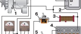
Scheme of electrical equipment URAL-6370
- 1. Car tachograph
- 2. Engine block interface (BDI)
- 3. Block of control lamps
- 4. Cruise control switch
- 4. Cruise control switch
- 5. Starter and instrument switch
- 6. Steering column switch for cornering and headlights
- 7. Steering column wiper and washer switch
- 8. Electronic speedometer
- 9. Voltage indicator of the on-board network
- 10. Electronic tachometer
- 11. Coolant temperature gauge
- 12. Oil pressure indicator in the engine lubrication system
- 13. Fuel gauge
- 14. Two-pointer pressure gauge
- 15. Auxiliary brake switch
- 16. Center differential lock switch
- 17. Unloading area light switch
- 18. Rear fog light switch
- 19. Cross-axle differential lock switch
- 20. Outdoor light switch
- 21. Relay breaker direction indicator
- 22. Remote switch "mass"
- 23. Alarm switch
- 24. Relay rear fog lights R13
- 25. Cabin lift switch
- 26. Pump motor
- 27. Sensor open grille
- 28. Thermal bimetallic fuse
- 29. Cab lifting relay
- 30. Cab heater valve.
- 31. Cabin heater motor
- 32. Electrically controlled rear-view mirror, left
- 33. Turn signal repeater left
- 34.56. Cabin lights
- 35. Canopy for lighting the loading area
- 36.57. Door light switches
- 37. Front left contour lamp
- 38. Side marker lamp, left
- 39,40,41. Road train sign lights
- 42. Road train sign switch
- 43. Rear-view mirror control unit
- 44. Blocks for connection with an independent heater and heater
- 45. Illumination of the cabin heater control.
- 46. Cabin heater tap control switch.
- 47. Cabin heater motor control switch
- 48. Side marker lamp, right
- 49. Lantern contour front right
- 50. Electrically controlled rear-view mirror, right
- 51. EDC diagnostic switch
- 52. Diagnostic switch ODI
- 53. Portable lamp socket
- 54. Diagnostic connector
- 55. Right turn signal repeater
- 58. Platform lift switch
- 59. Tipper trailer control switch
- 60. Mirror heating switch
- 61. Accelerator pedal
- 62. Fuse box F1
- 63. Fuse box F2
- 64. Fuse box F3
- 65. Starter relay R1
- 66. Relay unloading terminal "15" R2
- 67. Relay unloading terminal "15" R3
- 68. Wiper relay R4
- 69. Additional relay for rear fog lights
- 70. Side light relay R6
- 71. Fuse box F4
- 72. Low beam relay R7
- 73. High beam relay R8
- 74. Horn relay R9
- 75. Stop signal relay R10
- 76. Fuse block F5
- 77. Fuse block F6
- 78. Relay for heating mirrors of a car URAL
- 79. Headlight range control unit
- 80. Brake pedal position sensor relay
- 81. Switch center differential RK
- 82. Power take-off switch
- 83. Additional power take-off switch
- 84. Transfer case gear button
- 85. Transfer case gear switch
- 86. Solenoid valve center differential
- 87. Low gear solenoid valve RK
- 88. PK neutral solenoid valve
- 89. Top gear solenoid valve
- 90. Solenoid valve by power take-off
- 91. Solenoid valve for additional power take-off
- 92. Windshield washer motor
- 93. Wiper motor
- 94.107. Additional high beam headlights
- 95.106. Fog lights
- 96. Left direction indicator
- 97. Left dipped beam module
- 98. Headlight corrector motor, left
- 99. Module high beam headlights with the size of the left
- 100.101. Sound signal
- 102. Module high beam headlights with the size of the right
- 103. Right headlight corrector motor
- 104. Right dipped beam module
- 105. Right direction indicator
- 108,109,116,117. Side marker lights
- 110. Rear right lamp
- 111.112. Unloading area lights
- 113. Rear left lamp
- 114.115. trailer outlets
- 118. Engine brake damper valve
- 119. Camshaft speed sensor
- 120. Pressure sensor URAL 6370
- 121. Low pressure and low temperature sensor top
- 122. Oil pressure and temperature sensor
- 123. Boost pressure and temperature sensor
- 124. Camshaft speed sensor
- 125. Fan control valve
- 126. Fan speed sensor
- 127. Ambient temperature sensor
- 128. Fuel measuring device
- 129,150,131,132,133,134. fuel injection nozzles
- 135. Electronic control unit
- 136. Heating element preheating air
- 137. Relay preheating air
- 138.139. Heating elements for heating the fuel fine filter
- 140. Fuel heating thermostat
- 141. Air dryer heating element
- 142. Water level sensor in fuel
- 143. Heating element for fuel heating in the coarse filter
- 144. Starter
- 145. Generator
- 146. Fuel level sensor
- 147.148. Batteries
- 149. Switch "mass"
- 150.151. Wheel lock sensors
- 152. The sensor of inclusion of interaxal blocking of RK
- 153. Downshift switch RK
- 154. The sensor of inclusion of a box of selection of power
- 155. Interaxal lock sensor
- 156. Air filter clogging sensor
- 157.158. Pneumatic brake signal switches
- 159. Electro-pneumatic valve lifting dump trailer
- 160.161. Platform lift electropneumatic valve
- 162,163,164. Emergency air pressure sensors
- 165. Parking brake sensor
- 166. Speed sensor
- 167. Neutral sensor
- 168. Clutch sensor
- 169. The sensor of inclusion of a signal of a backing
- 170. Electro-pneumatic valve for inter-axle blocking
- 171. Electro-pneumatic valve interwheel lock
