The UAZ 469 car starter performs an important mission. It takes over the charging current from the battery (battery) and starts the car engine. Before the advent of the starter, the motor was started with a special steel handle. Through the radiator grill with two hooks, it was inserted into a ratchet connected to the crankshaft. Rotating the handle clockwise, the driver spun the crankshaft. At this moment, the carburetor sucked in gasoline, the ignition coil sparked the candles, and the engine started.
Starter UAZ 469: device and repair
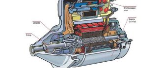
Photo 1: Starter UAZ 469 (Source: Yandex. Pictures)
Starter UAZ 469
Power units for Russian cars UAZ 469 are produced by two enterprises. These are Ulyanovsk and Zavolzhsky motor plants. The engines are equipped with starters in both companies by OOO Pramo-Electro, Rzhev, Tver Region. From here, engine builders receive a UAZ 469 starter under the factory catalog number 42.3708.
The starter of the UAZ-469 car is an electric motor that consumes direct current. It contains a series excitation winding. An electromagnetic traction relay and a drive with a freewheel are installed. It is installed on the left side of the engine.
Now the Rzhev plant has mastered the production of a more modern device. The improved car starter received a new catalog number 4211.3708-01. The driver turns on the starter with the ignition switch remotely. By turning the key in the ignition, he closes the DC circuit.
Electric energy from the battery begins to flow to its primary winding, exciting it. At the same time, the retractor relay pushes the working gear. It engages with the toothed flywheel of the engine, making a rotational movement. The flywheel spins up, all working parts move, the power unit starts.
Auxiliary VR starter
On modern cars, a priori, an additional VR starter is provided. On older cars, the relay is installed and connected already independently.
The advantages of installing an additional VR are obvious:
- Protects the starter device from burning out the contacts in the lock, which occurs for various reasons (long start, banal wear, etc.);
- It has a positive effect on the loading of the contacts of the same ignition switch, as a result of which the contacts remain operational longer;
- Protection of the starter from a situation when, due to a “glitch” of the key in the ignition (the engine starts, but the starter continues to spin).
You can check if the auxiliary BP is installed on the car as follows:
- Look in the "black box" (fuse box);
- Turn on the starter device in the motor purge mode - if the auxiliary relay is on, then the starter must turn off on its own after a few seconds.
Connecting an additional BP
Here's how the connection is made:
- Fix the relay in any convenient place (it is possible on the pin of the glass cleaning fluid tank);
- Connect the cable to the starter;
- Remove the red wiring from the flat terminal of the main relay, and insert the wiring from the auxiliary BP in its place;
- Connect the other wire of the new BP with an 8 mm tip to the plus of the starter;
- Put contact 30 of the additional TS on the released contact of the main TS;
- Screw the short wire number 85 to the body (ground).
Additional relays can be purchased from stores. They are sold in a kit, where everything is provided for proper self-installation.
Forget about fines from cameras! Absolutely legal novelty - traffic police camera jammer, hides your numbers from the cameras that are in all cities. More details at the link.
- Absolutely legal (Article 12.2);
- Hides from photo-video recording;
- Suitable for all cars;
- Works through the cigarette lighter socket;
- Does not cause interference to radios and cell phones.
And so today, while my girlfriend was riding a "Sotka" and died out, our ignition stopped responding, because it all started in the morning, after washing the engine, a new relay was bought in advance, the seller said that all the relays are the same, I believed him and bought a standard one five pin relay.
But it wasn’t there, the circuit of a standard relay is completely different. And when I tried to turn on the ground, the starter just simply started spinning, at that moment I compared the circuits on the relays. I put a dead relay, pushed it, started it, went around the clock. There, at my request to give the necessary relay and after showing a photo of what was needed, with a detailed explanation of the scheme of work:
Device
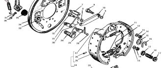
Photo 2: UAZ 469 starter diagram (Source: Yandex. Pictures)
Starter UAZ 469 number 42.3708 consists of the following elements:
- drive side cover;
- leash ring;
- thrust ring;
- lock ring;
- drive unit;
- anchor;
- frame;
- brush;
- traverse;
- thrust washer;
- adjusting washer;
- lock washer;
- cover on the collector side;
- contact bolt;
- contact plate;
- relay cover;
- return spring;
- stock;
- relay armature;
- compensating spring;
- buffer spring;
- gear;
- screw M5x14;
- tie rod nut;
- screw M6x16;
- nut M8;
- input of relay coils;
- screw M6x30;
- lever arm;
- nut M8;
- lever axis.
UAZ starter diagram
Starter 42.3708: 1 - drive side cover; 2 - driving ring; 3 - thrust ring; 4 - lock ring; 5 - drive; 6 - anchor; 7 - body; 8 - brush; 9 - traverse; 10 - thrust washer; 11 - adjusting washer; 12 - lock washer; 13 - cover from the side of the collector; 14 - contact bolt; 15 - contact plate; 16 - relay cover; 17 - return spring; 18 - stock; 19 – relay armature; 20 - compensating spring; 21 - buffer spring; 22 - gear; 23 - screw M5x14; 24 - tie rod nut; 25 - screw M6x16; 26 - nut M8; 27 - input of relay coils; 28 - screw M6x30; 29 - lever; 30 - nut M8; 31 - lever axis
Starter connection diagram
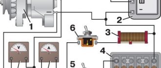
Photo 3: UAZ 469 starter connection diagram (Source: Yandex. Pictures)
UAZ 469 42.3708 starter connection diagram in the car's on-board circuit:
- "mass" switch;
- rechargeable battery;
- additional starter relay;
- ignition switch (lock);
- voltmeter;
- contact disk;
- retracting winding;
- holding winding;
- starter traction relay UAZ 469;
- starter UAZ 469.
Scheme of inclusion in the starter circuit
Scheme of inclusion of a starter: 1 – the switch of "mass"; 2 – storage battery; 3 – additional starter relay; 4 - ignition switch (lock); 5 - voltmeter; 6 - contact disk; 7 - retracting winding; 8 - holding winding; 9 – starter traction relay; 10 - starter
Starter 42.3708 or 4211.3708–01 with electromagnetic traction relay and lever drive with freewheel roller clutch is installed on the left side of the engine (in the direction of the vehicle). The starter switching circuit is shown in the second picture.
Specifications
The direction of rotation is right.
Rated voltage 12 V.
Power when powered by a 60 Ah battery 1.2 kW 1.65 HP
Idling at 20 °C:
- consumed current, no more than 75 A.
- voltage at the starter terminals, not more than 12 V.
- Rotor speed, not less than 5000 min -1.
Full braking at 20°C:
- braking torque, 1.6±0.16 kgf•m
- consumed current, no more than 520 A.
- voltage at the starter terminals, not more than 7 V.
Service starter UAZ 469
UAZ 469 starter service:
1. Periodically check the condition of the clamps on the contacts in order to prevent their weakening, ingress of dust, dirt, corrosion, and oxidation.
2. Inspect the collector, remove the protection cover. Eliminate the identified defects, clean the contacts, lubricate with Litol grease.
3. Open cover 13, check all elements. Clean contacts, blow with compressed air.
4. Tighten the UAZ 469 starter mounting bolts.
5. When operating a vehicle in a forest, quarry, countryside, it is necessary to periodically dismantle the UAZ 469 starter, clean it with a metal brush from dust, dirt, plaque.
10000 km
Check the UAZ 469 starter, perform TO-1 with the following routine operations:
1.Check the wires.
2. Tighten loose connections if necessary.
3. It must be remembered that a violation of the tightness of the wire from the battery to the starter leads to an increase in the transient resistance in its circuit.
4. As a result, it reduces power, impairs starting.
30000 km
Check the UAZ 469 starter, perform TO-2 with operations:
1. Remove the protection tape.
2. Blow out the manifold with compressed air.
3.Check brushes and commutator.
4. Eliminate defects.
Once every year, but at least 25,000-30,000 km of a car’s run, it is necessary to remove the UAZ 469 starter. It should be disassembled, thoroughly wiped and blown out with compressed air. If defective parts, assemblies, mechanisms are found, replace them with new ones or repair them. Collect, adjust, check.
Popular starters for UAZ Loaf
The original starter for "Loaf" has a gear contraction, which ensures that the engine flywheel is turned for a successful start. The minimum allowable power of the device for UAZ "Loaf" is an indicator of 1.8 kW / h - equipment of lower power will either not provide the proper level of functioning, or will quickly fail.
| Manufacturer | vendor code | Device type | Machine power kW/h | Approximate cost, rub. |
| 'BATE' | 5112.3708 | geared | 1.8 | 4100 |
| 'BATE' | 5112.3734 | geared | 1.8 | 4200 |
| ZMZ | 5732.37080004 | geared | 1.8 | 4300 |
| ZMZ | 5732.34308000 | geared | 1.8 | 4350 |
| UAZ | 5732.3342000 | geared | 1.8 | 4500 |
| UAZ | 5732.3758000 | geared | 1.8 | 4550 |
| UAZ | 5732.3732000 | geared | 1.8 | 4650 |
Do not try to save on the quality of the device - purchase only the original kit or proven analogues from reliable suppliers or at an official dealership. Remember, the wrong type of starter can significantly shorten the life of the engine.
Note! Before purchasing the device, you need to check the part for compatibility with the car - to do this, check the part number with the VIN number of the vehicle on the official website of the manufacturer. This step will protect against the acquisition of the wrong type of components and possible failure of the engine's electrical systems.
Do-it-yourself UAZ 469 starter repair
When repairing the UAZ 469 starter with your own hands, it is necessary to carry out the steps for dismantling, cleaning, replacing worn parts, subsequent installation and adjustment, described below.
Removal and installation of a starter
The starter is disassembled in the following sequence:
- Unscrew the M8 nut, pos. 26, disconnect the output from the contact bolt pos. 14.
- Loosen the screws pos. 28, remove the relay.
- Loosen the nuts pos. 24 on tie rods.
- Loosen the two screws pos. 25, remove the cap.
- Remove the locking, adjusting washer pos. 11 and pos. 12.
- Remove cover pos. 13.
- Pull out the brushes pos. 8 of the brush holders and remove the traverse pos. 9.
- Remove the housing pos. 7.
- Unscrew the nut securing the lever axle, unscrew the lever axle pos. 31, pull out the lever pos. 29.
- Pull out the anchor pos. 6.
- Move the thrust ring pos. 3, remove the locking ring pos. 4 and then the drive pos. 5.
- To inspect the contacts, unscrew the two screws pos. 23, unsolder two inputs pos. 27, remove the relay cover pos. 16.
Assembly is carried out in the reverse order.
Frame
Check with a control lamp whether the coils in the excitation winding are shorted to the body. Connect one of its wires to the case, connect the second to the output. The lamp caught fire - it means that the insulation is damaged. To eliminate this defect, it is necessary to immediately number the poles, unscrew the fixing screws, and remove the coils.
Wrap damaged areas with a new layer of insulating material. Fix the poles in regular places. Point the screw heads to prevent unintentional unscrewing.
Manifold side cover
Check with a control lamp the short circuit to the body of the insulated brush holders. If a short is found, replace the insulating gasket. You should also check the rivet bushing. Inside the glasses, the brushes should move easily, without effort. Check the bearing bush located in the cover. Replace worn bushing.
The cross section of the hole in the new bushing after it has been pressed into the cover and reamed should be 12.5 + 0.035 mm. Surface roughness grade 8. If the brushes are worn out with a height of less than 6-7 mm, new ones must be installed.
Rotor
The rotor is checked either with a special device or with a test lamp. The purpose of the test is to determine if there is a short circuit of the rotor winding on the iron package. One terminal is connected to any lamella of the rotor, the other - to the iron package of the rotor. The signal lamp should not light up.
The rotor should be carefully inspected from all sides. At the front, the rotor winding is made in a section smaller than the iron package. If its diameter has managed to increase, you should be wary. The front part of the winding of increased diameter indicates the "spread" of the winding. Such a rotor must be replaced.
The wire lugs of the windings must be securely soldered to the collector terminals. The next check is that there are no short circuits between the turns of the rotor. If a short circuit is detected, the rotor must be replaced. The rotor manifold must be clean.
If an insignificant roughness of the collector is noticeable or mica protrudes slightly, it must be machined on a turning, milling or other special machine. After turning, the collector should be ground with a glass sandpaper with a grit of 100 to a surface roughness of class 7.
The total runout of the collector relative to the shaft trunnions should not exceed 0.05 mm. The runout of the iron package of the rotor relative to the pins of the shaft should not exceed 0.25 mm. At the same time, the shaft must be checked for deflection. The presence of any deflection can cause the drive to seize on the splined part of the shaft.
If there is a yellow coating from the bearing on the rotor shaft in the place where the starter gear rotates, then it should be removed with a fine sandpaper. The presence of a yellow coating often leads to seizing of the gear on the shaft after starting the engine and to the displacement of the rotor winding.
Drive unit
It is necessary to conduct an external inspection of the UAZ 469 starter drive for slippage. It should be completely free, not stick, freely and easily moving along the splined surface of the shaft. If there is excessive wear on the drive bearing bushes, they must be replaced.
When the rotor is held, its gear should rotate freely clockwise. Rotation of the gear counterclockwise is only allowed together with the rotor. Checking the freewheel for slippage should be carried out on a special stand when testing the starter for full braking.
Traction relay
Checking the holding and traction windings is carried out with an ohmmeter or resistance measurements with an ammeter and a voltmeter. Relays with faulty coils should be replaced immediately. The ends of the terminal bolts must be cleaned. If the tips have had time to burn out excessively, they should be turned 180 ° around their axis.
Strong wear of the contact disk must also be eliminated. To do this, it should be deployed with the surviving side to the contacts. The armature of the traction relay must move freely in the housing.
Starter malfunctions and methods for their elimination
There are typical breakdowns in which there is a certain troubleshooting technology. We offer owners of this popular model ready-made repair solutions.
When the starter is turned on, the armature does not rotate
| Cause of failure | Repair Methods |
| The brushes are not in contact with the commutator | Remove starter from engine. Perform a complete disassembly. Eliminate the cause of the malfunction. |
| No contact in the traction relay switch | Unscrew the electrical wires from the starter. Remove switch cover with contacts. Carefully clean burnt contacts. If the contacts are too burnt, turn the cover 180°. |
| The connecting contacts of the traction relay are destroyed or inside the starter | Dismantle the starter and take it to a workshop for professional repair. |
| There is no stable contact of the ignition switch on the terminal "B" | Check the electrical circuit with a test lamp. To do this, connect the lamp to the contact "C" and ground. If there is no voltage on terminal "C" when the ignition switch is on, it must be replaced with a new one. |
| Breakage of the winding, burning of the contacts of the auxiliary relay | Check the electrical circuit with a test lamp. When the starter is turned on, the control lamp connected to the contact "K" of the additional relay and ground should light up. If this does not happen, you should disassemble the relay and clean the contacts. |
| Wedged armature inside the sleeve of the electromagnet coil | Clean the starter anchor, bushing and relay from dirt, rinse in clean kerosene. If the traction relay is misaligned relative to the starter lever, it is necessary to take them to a workshop for professional repair. |
When the starter is turned on, the engine crankshaft does not rotate or rotates at a low speed
| Cause of failure | Repair Methods |
| Faulty or discharged battery | Check battery. Recharge or replace. |
| Short circuit of excitation coils or armatures. The anchor can touch the poles. | Eliminate the short circuit or send the starter to the workshop. |
| The crankshaft of the engine turns with difficulty. | Warm up the engine in winter. |
| Wire lugs loose. Because of this, the starter power circuit is broken. | Tighten the clamps, carefully inspect the entire electrical circuit. |
| Excessive bearing wear. | Dismantle the starter and send it to a workshop for professional repair. |
When turned on, the starter shaft rotates at a high speed without turning the engine crankshaft
| Cause of failure | Repair Methods |
| The destruction of the gearing of the flywheel crown | Ring gear replacement |
| Freewheel roller clutch slip | Starter drive replacement |
When the starter is turned on, a repeated strong knock of the traction relay and gear on the ring is heard, but the engine crankshaft does not turn
| Cause of failure | Repair Methods |
| Lack of contact between the clamps, in particular on the battery. | Tighten the clamping bolts, check the power supply circuit. |
| Faulty or discharged battery. | Replace battery or charge. |
| Breakage of the holding winding of the traction relay. Weak ground contact. | Replace the winding or ensure its reliable contact with the ground. |
After starting the engine, the starter does not turn off
| Cause of failure | Repair Methods |
| Lack of contact between the clamps, in particular on the battery. | Tighten the clamping bolts, check the power supply circuit. |
| The drive is wedged on the armature shaft. | Dismantle the starter, eliminate the cause. |
| On the traction relay or on the additional relay, the contacts of the switch are baked. | Repair or replace the relay. |
