The electrical circuit of the car MAZ
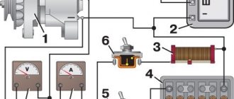
Two variants of wiring diagrams for MAZ vehicles. All schemes are presented in the form of small copies - to enlarge, click on the image and download to your computer.Wiring diagram MAZ - option 1
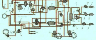
1 FG119-3711000-V Fog lamp 3 MM350B-3810000-G Sensor for oil and air pressure indicator MM-350B 4 SK-RR127-3702000 Relay-regulator assembly 5 PF101-3712000-V Sidelight assembly 6 500-3724342-G bundle wires of the right sidelight 7 FG-122-3711000-V Headlight 8 PS5-3723000 Five-terminal connecting panel 9 PZhD400-1015410-B Heater control panel 10 500-3724045-B2 Bundle of wires between headlights 11 SL108-5205000-G Electric windshield wiper S L-108 12 SK101-3721000 Two-tone sound signal assembly 13 500-3724086-B Engine heater wire harness 14 500A-3724030 Side member wire harness 14 503A-3724030 Side member wire harness 14 504A-3724030 spar 15 G270A-3701000-G Generator in assembly 15 SK-ST103-3708000 Starter assembly 16 SK-P39-3710000 Foot-operated light switch 18 500-3724058-V Starter wire bundle 20 500-3724064-G Cabin and engine ground connection wire 21 PS12-3723000 Twelve-terminal connecting panel 2 2 ME233 -3730000-G Heater electric motor 23 51-3723100 Connecting wire coupling assembly 24 500-3724080-B1 Heater electric motor wire 25 PR102-3722000-B Fuse block with fusible inserts, assembly 26 PR102-3722000-V Fuse block from fuse with inserts 27 PC401 -3726000-G Direction indicator interrupter RS-401 28 500-3724010-Zh1 Main wire harness 29 500-3724062-E Wire from batteries to starter 30 KP-118-3801000-G Instrument panel assembly 31 UK-143 Water temperature indicator 32 UK-144 Air and oil pressure gauge 33 SP-134 Speedometer 34 PP127-3713000-B Bulb holders 35 UB-125 Fuel level gauge 36 PD20-3803000-P Direction indicator pilot lamp 37 SK-VK26-3720000-A2 Instrument switch , windshield wipers and fog lights 38 SK-P20-3710000-A2 Lampshade, heater and fuel tank switch 39 PP2-3713000 Low beam control lamp holder. Lamp L28x1 40 500-3724073-V1 Wire from instrument switch to instruments 41 G-P38-3709000 Light switch 43 AP-109 Ammeter 44 500-3724050-G1 Wiring harness for ceiling lamps 45 504-3724022-V Bundle of wires for fuel gauge 45 504B- 3724023-B1 Fuel gauge wire 47 500-3721080-B Signal contact device assembly 48 SK-P109-3709000-B2 Turn indicator switch 49 ME302V-3730000-G Speedometer sensor 50 6TB.266.003 Portable lamp socket 51 SK -VK318- 3704000-B Battery ground switch 52 500-3724052-B Ground wire for portable lamp outlet . . 53 500-3724039-B Power cord for portable lamp socket 54 500-3724057-D Battery jumper 55 501-8104210 Driver blower 56 PK201-3714010-A Cabin lighting dome 57 PS4-3723000-A2 Two-terminal connecting panel 58 SK-BM 127- 3806600-A Fuel gauge sensor 59 SK-VK13-3720000-B Stop signal switch 60 FP101-3716000-G Rear right lamp assembly 61 PS1-3723000-A2 Three-terminal connecting panel 61 PS2-3723000-A2 Four-terminal connecting panel 62 500-3724031-V1 Bundle of wires of the left rear lamp and trailer socket 62 503А-3724032 Bundle of wires of rear lamps 63 PS300-3723100 Trailer plug socket 64 FP101-3716000-В Left rear lamp assembly 65 PK201-3714010-А Plafond of illumination of the engine 66 FYu3 -552-030 Battery 6TST-165EMS 67 500-3724069-V Wire from the battery to the mass switch 68 SK-TM100-3808000-G Water temperature indicator sensor TM-100 69 SK-RS512-3721000 Signal relay 73 500-3724058- D Bundle of starter wires (when installing a preheater) 75 UP101-3726000-B Repeater of the side direction indicator 76 500-3724160 Bundle of wires for the engine assembly 77 500-3724032-G1 Bundle of wires for the right rear light 78 500-3724041-A1 Bundle of wires in the opposite direction semolina headlights
Wiring diagram MAZ - option 2
Al - Fuse and relay box, A3 - Wiper breaker, A6 - Turn indicator breaker, A7 - Radio, A8 - Demultiplier blocking relay, BAI, BA2 - Loudspeaker, VK - Temperature sensor, VR1.VR2 - Air pressure sensor, VRZ - Sensor oil pressure, VR4.VR5 - Emergency air pressure sensor, BPI0 - Emergency oil pressure sensor, BV2 - Speedometer sensor, BV3 - Speed sensor, EKZ, EK4 - EFU candle, E1, E2 - Headlight, EZ, E4 - Fog headlight, E5, E6 - Front light, E7 - Light, E8 - License plate light, E9 ... E11 - Road train sign light, EI2 - Body light, E13, E14 - Side direction indicator, EI5.EI6 - Clearance light, E17, E18 - Rear lantern, E20 - Reversing lamp, E23.E24 - Cabin illumination lamp, E25 - Engine lamp lamp, E26 - Headlight - searchlight, E28, E27 - Sleeper lamp lamp, EK1, EK2 - Shelving lamp, EZO - Mirror heater, EL1 ... EL6 - Instrument illumination lamp, FU1 - Fuse 60 A, FU2 - Fuse 30 A, FU3-FU9 - Fuse 8 A, FU11 - Fuse 16 A, G - Generator, GBl, GB2 - Battery 6CT I90A, ON 1 - A set of electrical signals, HA2 - Pneumatic signal, KK1 - Additional resistance, KK2 - Parking brake indicator breaker, K1 - Starter relay, Ml - Starter, M2, MZ - Heater motor, M4 - Wiper motor, M8 - Washer motor, PP - Instrument cluster, P2 - Tachometer, PS - Speedometer, RP - Backlight rheostat, XSl - Main socket, XS3 - Socket, XS4 - Portable lamp socket in the cab, XS5, XS6 - Socket, WA - Antenna, SA1 - Starter switch, SA2 - Wiper switch, SA3 - Main light switch, SA4 - Turn signal switch, SA5 - Heater switch, SA7 - Light switch, SA8 - Dome light switch, SB1, SB3 - Push button switch, SB4 - Alarm switch, SA9 - Hydroselection valve switch, Push button illuminated switches: SB5 - Fog lights, SB8 - Neutral switch, SB9 - Engine light, SB11 - Searchlight headlight, SB12 - Axle differential, SB13 - Axle differential, SB 14 - Road train lights, SB 15 - Heated mirrors, SB20 - Rack lighting, SK - Emergency temperature sensor, SLI - Fuel level sensor, SP1.SP6 - Stop signal switch, SP7 - Switch, SQ1, SQ2 - Switch.
Control lamps: HG1 - Control lamp block, HG4 - Tractor turns, HG5 - Trailer turns, HG7 - EFU systems, HG8 - High beam, HG9 - Divider switch, HG10 - Interaxle lock, HG11 - Interwheel lock, HG12 - Neutral switch.
CAR ELECTRONICS REPAIR
How to connect the MAZ generator?
When washing the engine, it is recommended to protect the generator from water ingress. Each phase consists of twelve coils connected in series, arranged on separate poles for a total of 36 poles.
The brush holder also has a make-up resistance 3 of 75 Ohm, which serves to ensure reliable excitation of the generator set at low engine speeds. Disconnecting the battery during operation of the power unit reduces the load and leads to a malfunction of the YaMZ generator. The replacement of the failed regulator and brushes must be carried out in the workshop.
If the indicated measurements deviate from the required limits, it is necessary to determine and eliminate the malfunction of the vehicle's on-board network. MAZ generator connection diagram Publication date: The maximum excitation current for which the design elements of the regulator R are designed is 3.3 A.
This is done in order to unload the contacts of the EPS, since the current during the initial excitation of the generator can reach 5 A. The generator set is a three-phase twelve-pole synchronous electric machine with a built-in rectifier unit, an interference suppression capacitor, a brush holder with a voltage regulator and a system with exhaust ventilation. In addition to direct functions - generating electricity to supply the electrical equipment of a car, one more requirement is imposed on modern generators - it should not affect and respond to radio waves.
The core is assembled from plates of electrical steel, insulated from each other with varnish and connected by welding along the outer surface of the package. And it is required for the ignition system, on-board computer and now various gadgets, diagnostic and control devices, and of course for lighting, both signal and household.
With an increase in the rotor speed, the generator voltage can reach a dangerous value for receivers, so the generator works in conjunction with a voltage regulator that maintains the voltage in the car's on-board network within the specified limits. Since the electric motor works for a short time, it ensures the normal operation of the heater during vehicle runs during several overhauls. The generator is excited from the current of an independent source - batteries. During operation, check the belt tension and follow the wear of the components. The waterproof design of the generator is ensured by the use of appropriate coatings on the surface of its parts and impregnation of the windings with waterproof varnishes.
The generators of the MAZ car models and are powered by additional diodes. If the voltage increases or decreases, the regulator reduces or increases the excitation current accordingly and introduces the voltage within the required limits. Rotor 17 is a shaft with a pressed-on laminated package and a bushing. It is impossible to check the health of the electrical circuit and individual wires with a megger or a lamp, which is supplied with voltage above 26 V, with the generator not turned off. After assembly, the circuit is closed with a lid and filled with a special sealant.
On another small-sized ceramic board, there are crystal structures of the transistor of the terminal stage T2, the output transistor T3 and the quenching diode D1. Incorrect connection of wires and terminals causes failure of the rectifier diodes. When checking the generator on a car, it is necessary to reconnect the wires and connect the devices for testing with the mass switch off. The output is intended for connecting a tachometer and other devices of the starter blocking relay, ABS, etc., critical to the shape of the phase signal. Phases of the stator winding of the generator armature Scheme for connecting a backup generator to the house. Reversing switch connection diagram
Maintenance, malfunctions and repairs
The main malfunctions and repair of electrical equipment:
- The indicator lamps are out of order. In this case, it is recommended to check the reliability of the contact in the detachable connections, inspect the safety device for damage and defects, check the integrity of the backlight rheostat and the integrity of the relay.
- The lights do not come on when reverse gear is engaged. In this case, you should eliminate the short circuit in the wiring of the lamp, check the reliability of the contacts, connect the harness to the reverse sensor, inspect the lamp for defects, and align the wires in the block.
- The rear brake lights do not come on. The problem may be related to an open circuit, a short circuit, a malfunction of the brake signals, a break in the filament of an incandescent lamp.
- The headlights don't light up. It is necessary to inspect the electrical wiring for a short circuit, conduct an external inspection of the switch (if damage is found, replace it), check that the relay is in good condition.
- Heated mirrors are not working. You should inspect the contacts in detachable connections, check the fuse for wear, replace damaged parts in the system.
- The headlights are constantly on. In this case, you need to check the health of the switch, the reliability of the contacts in the pads, and inspect the relay for defects.
- The direction indicators do not light up. It is necessary to replace the lamps, inspect the breaker, replace the BKA.
- The tachometer is out of order. A malfunction may be caused by a malfunction of the sensor, a safety device, or unreliable contacts in the pads.
Read more: What kind of certificate is enough to have a driver manager
Maintenance is carried out after 50,000 km of run . For the correct operation of all mechanisms of electrical equipment, it is not recommended to disconnect the wires from the positive terminal and from the battery, check the functioning of the systems by closing the terminals or with a megohmmeter.
MAZ vehicles have a 24-volt electrical system unified with the main models and modifications.
The electrical equipment of MA3-54322, MAZ-64227 vehicles differs from the electrical equipment of MAZ vehicles of previously produced models by the saturation with various control devices, lamps and signaling devices that allow assessing the condition of the vehicle's units and systems. The operation of the vehicle systems is controlled by light signaling devices, and in some cases by a noise relay. Below are the necessary information on the design features, maintenance and repair of electrical equipment of cars.
On all the diagrams given in the section, the colors of the wires are marked with letters: B - white, D - blue; Zh - yellow; O - orange; P - pink; C - gray; 3 - green; K - red; Kch - brown; H - black; F - purple.
In order to facilitate troubleshooting, the circuits on the diagrams have a digital indication, which is also indicated on the wires.
About the scheme of the block BSK-4
On many forums, owners of dump trucks, MAZ trucks are often asked to show a photo of the BSK 4 scheme.
However, this scheme is not placed in the manuals for the operation of cars.
Usually it is necessary to repair the unit.
The process of troubleshooting, soldering parts is extremely complicated.
The fact is that even a professional is difficult to replace all the constituent elements with a guarantee of further work.
Therefore, if your BSK-4 block is broken, we advise you to buy a new one. Repairing parts is extremely dangerous.
Purpose of the MAZ block
Thanks to the modern BSK 4 MAZ (multilayer printed circuit board), the circuits of the electrical equipment of Belarusian trucks are protected from overvoltage.
The manufacturer of the part is OAO MPOVT.
The high quality of the block complies with international standards.
Thanks to the well-established production and application of the latest technologies, the BSK 4 MAZ block has the following characteristics:
- Voltage - 24 ± 6 V;
- The mode of operation of the part is nominal S 1;
- Corresponds to GOST 3940;
- Temperature conditions - from -55 to +60 degrees Celsius;
- The function of increased protection against the ingress of liquid, dust and other foreign bodies is provided;
- Weight - 6.8 kg.
