Lubrication system of the ZIL-131 car engine
Military Encyclopedia - historical and archival military-patriotic portal
home☆soviet military encyclopedia☆military equipment☆military science☆military review☆arms history☆forum
military equipment ☆ articles on the BAT device ☆
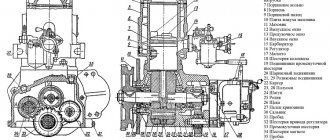
Fig.35. Scheme of the lubrication system of the ZIL-131 engine : a - general scheme; b - oil supply to the axes of the rocker arm; c - oil supply from the axis of the rocker arm to the tip of the rod; g - lubrication of the cylinder walls; 1 - oil supply pipe to the oil cooler; 2 - radiator shut-off valve: 3 - lubrication pump: 4 - oil supply channel to filters; 5 - oil distribution chamber; b - centrifugal oil filter; 7 - compressor; 8 - left main channel; 9 - oil supply pipe to the compressor; 10 - pipe for draining oil from the compressor; 11 - oil cooler; 12 - tube for draining oil from the radiator; 13 - oil receiver; 14 - dirt collector; 15 - right main channel; 16 - channel in the rack of the rocker; 17 - axis of the rocker; 18 - hole in the connecting rod; 19 - oil pressure indicator; 20 - control lamp.
This system (Fig. 35) consists of an oil filler pipe, a pump pan with an oil receiver, a filter, a radiator, an oil level indicator, lines, pipelines, and control devices. Lubrication pump 3 gear, two-section, driven by a gear on the camshaft, mounted in the rear of the engine on the right side (in the direction of the vehicle). The upper section of the pump supplies oil to the lubrication system, and the lower section through the valve to the radiator. The upper section of the pump has a pressure reducing valve that maintains a system pressure of 320 kPa; in the lower section of the pump there is a valve adjusted to a pressure of 120 kPa.
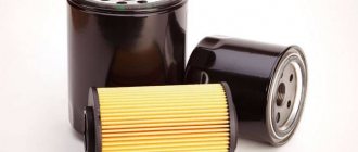
Jet driven centrifugal oil filter 6, full flow, mounted on the cylinder head cover at the top rear. The filter has two jets (nozzles) that eject oil in jets in opposite directions, which ensures the rotation of the rotor assembly with the cap at high frequency and centrifugal cleaning of the oil. A correctly working centrifuge continues to rotate after the engine stops for 2 ... 3 minutes, while a peculiar sound is heard. If the filter is clogged or the oil viscosity is high, it enters the system without cleaning through the bypass valve installed in the filter housing.
Oil cooler 11 air-cooled from a silver-plated aluminum tube, installed in front of the radiator of the engine cooling system. The valve 2 for turning on the radiator is located in the housing of the lower section of the lubrication pump. During the operation of the car in the spring and summer period, valve 2 must be open.
The oil level gauge is installed on the right side of the engine. There are three marks on its stem: "Full", "Full" and a rectangle mark above the "Full" mark.
The pressure in the lubrication system is controlled by a direct-acting diaphragm pressure gauge, it has contacts for turning off the emergency pressure drop lamp. The pressure gauge and lamp are installed on the instrument panel.
When the engine is running, the top section of the pump delivers oil through a channel in the rear baffle of the block to the filter. The purified oil enters the distribution chamber 5 in the rear partition of the block, from where it enters two longitudinal main channels 8 and 15. From the right channel, the oil is supplied to the crankshaft main bearings, and from them to the bearings and the camshaft thrust flange. Channels in the crankshaft supply oil to the connecting rod bearings. When the hole in the connecting rod body coincides with the channel in the shaft neck, oil is sprayed onto the cylinder wall. Through two radial holes in the neck of the middle bearing of the camshaft, oil is periodically supplied through the channels in the cylinder block, block heads, racks and rocker axles to the rocker arm bushings, and through the holes in the rocker arms to the upper tips of the rods. The pushers are lubricated with oil from the longitudinal main channels. From the front end of the left main channel, oil is supplied to lubricate the compressor, and from it, through pipeline 10, flows into the crankcase. The pressure in the lubrication system must be 200 ... 400 kPa.
Rice. 36. Scheme of ventilation of the crankcase of the engine ZIL - 131 : 1 - air filter for crankcase ventilation; 2 - oil catcher; 3 - ventilation valve; 4 - tap for shutting off ventilation.
The crankcase ventilation (Fig. 3b) is closed, with the suction of crankcase gases through the oil trap 2, valve 3 and the tube into the inlet pipeline, where they are mixed with the combustible mixture and enter the engine cylinders. The oil catcher separates oil droplets from gases. When the engine is idling, when the vacuum in the intake manifold is greater, the valve ball 3 rises and the flow area decreases; when working under load, the vacuum decreases, the valve ball drops under its own weight and the flow area increases; thereby regulating the amount of exhaust gases from the crankcase.
Fresh air enters the crankcase through filter 1 installed on the oil filler pipe.
Before crossing the ford, ventilate the shut-off valve using a crane 4. While crossing the ford, the crane handle must be located vertically, all the rest of the time it must be in a horizontal position.
Tags: zil 131 ☆ lubrication system ☆ car device ☆
| The lubrication system of the engine of KamAZ-4310 and Ural-4320 cars < Prev. | Track. > Maintenance of the lubrication system |
We will quickly provide a tow truck in the city of Odintsovo
In Moscow and the Moscow region
- Contacts:
- +7
- around the clock
- seven days a week
© Military Encyclopedia. Map of site.
Lubrication system device
The lubrication system of V-shaped engines is mixed (under pressure and splashing). On fig. 1, a shows the engine lubrication scheme, equipped with a partial flow filter (centrifugal filter and coarse oil filter), and in fig. 1, b - scheme with a full-flow centrifugal filter (without a coarse oil filter). The design of the full-flow centrifugal oil filter is more perfect.
Its installation on the engine began in the second half of 1967.
To cool the oil, an oil cooler is installed in front of the water cooler. Under pressure, oil is supplied to the main and connecting rod bearings of the crankshaft, to the camshaft bearings, to the bearings of the drive shaft of the breaker-distributor and oil pump, and to the pushers. To the bushings of the rocker arms, oil is supplied with pulsating pressure through the hollow axle of the rocker arms, into which oil enters through channels 8 coming from the middle bearing of the camshaft. Oil is supplied to the rest of the rubbing parts of the engine by gravity and splashing.
From the crankcase, oil is sucked through a fixed oil receiver 17 into the oil pump 3. Through the channel 4 in the rear bulkhead of the block, the oil pump supplies oil to the oil filter housing, where the entire flow passes through the coarse plate filter 5. From the coarse filter, part of the oil, about 50%, goes to the centrifugal oil filter 6, from where it drains into the oil pan.
The main oil flow from the coarse filter enters the distribution chamber 7 located in the rear bulkhead of the cylinder block. From the distribution chamber, the oil enters two longitudinal main channels 12 and 16y, from which it enters the crankshaft main bearings, and from them to the camshaft bearings. Through the drillings of the crankshaft, oil is supplied to the cavity of the connecting rod journal, where it is additionally cleaned and through the holes in the connecting rod journals it enters the connecting rod bearings.
In the presence of a full-flow centrifugal oil filter, all incoming oil is cleaned only in it, from where it is sent to the distribution chamber 7, and then to the longitudinal channels 12 and 16 and to the lubricated engine parts.
There is a hole in the lower head of the connecting rod, at the moment of its coincidence with the hole in the crankshaft journal, oil is sprayed onto the cylinder wall, from where it is removed by the oil scraper ring, then through the holes in the groove of the oil scraper ring it is discharged into the piston and lubricates the piston pin supports in the piston bosses and in the upper head connecting rod. From the front right end of the main channel 16, oil enters through the pipeline 13 to lubricate the crank mechanism of the compressor.
In the middle journal of the camshaft, two holes are provided, branched at an angle of 40 °, when they coincide with the holes in the cylinder block, once per revolution of the camshaft, oil for lubricating the valve mechanism enters channel 8, made in each cylinder head.
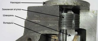
From channel 4 (Fig. 2) of the cylinder head, oil enters cavity 3 through the groove on the bearing surface of the axle strut and through the gap between the strut and the rocker arm axle bolt. - to the ball joint of the adjusting screws 6 with the rods 5 of the pushers. Through kaial 8, the oil flows to the surface of the cylinder head, and when it enters the openings for the rods, it drains into the oil pan.
The valve stems in the guide sleeve and the exhaust valve rotation mechanism are lubricated by oil mist and drops of oil flowing from the joints of the rocker mechanism by gravity.
On this topic:
Zil 131 and military-patriotic Sunday
Engine disassembly II
Rules for using the winch
Lubrication system ZIL-130
The lubrication system of the ZIL-130 engine is mixed: oil is supplied under pressure and splashing (Fig. 17). The oil is cooled in the radiator. Oil pump - two-section, gear. The upper section of the oil pump supplies oil to the engine lubrication system through a centrifuge, while the lower section supplies oil to the oil cooler. The pressure reducing valve built into the oil pump cover is adjusted to a pressure of 320 kPa (3.2 kgf / cm2), at least, and bypasses oil from the oil pump pressure cavity to the suction one. The bypass valve built into the body of the lower section of the oil pump is adjusted to a pressure of 120 kPa (1.2 kgf / cm2). Oil filter ZIL-130 (Fig. 18) - centrifugal, with a jet drive (centrifuge), included in the lubrication system in series. The filter housing 3 rotates under the action of the reactive force created by the jet of oil flowing out of the housing through two jets 1. The correct rotation of the centrifuge is checked by ear. After stopping the engine, a serviceable centrifuge continues to rotate for 2-3 minutes, while a peculiar sound is heard. Under the action of the emerging centrifugal forces, the mechanical particles in the oil are thrown to the side walls of the cover 5 of the body, on which they are deposited, resulting in a dense deposit. This sediment is removed when cleaning the centrifuge, at the same time as changing the oil in the crankcase. To clean the centrifuge, stop the engine and let the oil drain from the centrifuge for 20-30 minutes. Then it is recommended to do the following: 1) unscrew nut 15 and remove cover 8; 2) unscrew the plug in the body 21 and insert a rod into the hole that keeps the body from rotating; 3) unscrew the nut 14 of the cover with a wrench for wrapping candles, remove the cover 5 of the body together with the nut 14; 4) remove insert 7 of the centrifuge and strainer 6; 5) clean the removed parts from deposits and dirt, wash them, if the filter mesh is very resinous, if it cannot be washed and blown, and also if it breaks, the mesh filter should be changed; 6) clean the gasket 2 of the casing from dirt. Damage to the end of the casing adjacent to the gasket 2 is unacceptable, as it leads to oil leakage.
Rice. 17. Scheme of the lubrication system of the ZIL-130 engine: a - general lubrication scheme; b - oil supply to the axis of the rocker arm; c - lubrication of the adjusting screw and the upper tip of the rod; g - lubrication of the cylinder walls; 1 - oil pump; 2 - channel for supplying oil from the pump to the filter; 3 - oil distribution chamber; 4 - oil pressure gauge; 5 - control lamp for emergency oil pressure reduction; 6 - centrifugal oil filter; 7 - air filter; 8 - compressor lubricated by splashing; 9 - left main channel; 10 - oil supply pipe for compressor lubrication; 11 - pipe for draining oil from the compressor; 12 - crankshaft pulley; 13 - cavities for centrifugal oil cleaning and connecting rod journals of the crankshaft; 14 - right main channel; 15 - oil receiver; 16 - oil supply pipe to the oil cooler; 17 - valve for turning off the oil cooler; 18 - channel in the valve rocker arm; 19 - hollow axis of the rocker; 20 - hole in the connecting rod for supplying oil to the cylinder wall.
Actual:
Steering gear disassembly
ZIL-130 cooling system, water pump and ZIL-130 radiator
Differential

