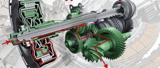
Clutch mechanisms in the "young years" of world engineering
The invention of the clutch mechanism is attributed to Karl Benz. Whether this is true or not, it is impossible to reliably establish: several companies were simultaneously engaged in the production and improvement of the first cars in the 19th century, and all of them followed their development, as they say, “nostril to nostril”. The oldest type of clutch, widely used on most cars of the late 19th and early 20th centuries, was a conical clutch. Its friction surfaces had a conical shape. Such a clutch transmitted more torque, with the same dimensions, compared to the current single-disk, it was extremely simple in its design and maintenance.
Comfortable "Mercedes Benz HP-50" - a car with a conical friction clutch.
However, the heavy conical disc of this type of clutch had a large inertia, and when shifting gears after depressing the pedal, it still continued to rotate at idle, which made it difficult to shift into gear. To brake the clutch disc, a special unit was used - the clutch brake, but its use was only half the solution to the problem, as was the replacement of one cone with two less massive ones. As a result, already in the 1920s, such a heavy and bulky (to whom it requires significant muscular effort to use) design, like a conical clutch, was completely abandoned. There was also a reverse cone clutch that worked to expand.
However, the very principle of this mechanism has found a new embodiment in the design of modern gearboxes with synchronizers. Transmission synchronizers are essentially small bevel clutches that work by rubbing bronze (or other high friction metal) against steel.
Clutch device
Several types of clutch mechanism have been invented. However, mechanisms based on the use of one or more friction discs, which are tightly compressed by springs with each other, or with a flywheel, have become the main and most widely used mechanisms. The friction material of these discs is similar to that used on brake pads.
The classic clutch mechanism consists of a driven and pressure plates, plus a drive that encourages them to press or simultaneously disconnect from each other. This design is fixed in a casing that is firmly attached to the crankshaft flywheel. The pressure plate is quite massive and is also firmly attached to the casing. The driven clutch disc is much thinner than the driven pressure disc and is located on the splines of the main (primary) shaft of the gearbox of a car or tractor. Splines provide its mobility along the axis of the shaft, as well as a rigid hitch with the shaft. The pressure plate does not have a hitch with the gearbox shaft.
The clutch disc is equipped with spring plates to which two friction linings are attached. The central part of the driven disk - the hub - is equipped with a spline connection and can move along the input shaft of the gearbox. The hub is movably connected to the main part of the disk by means of damper springs and friction washers of the torsional vibration damper.
All components of the clutch mechanism are located in the crankcase, which is bolted to the power unit. All clutch parts are covered by a casing (clutch basket) bolted to the flywheel; the axes of the release levers are attached to the casing through the lugs.
Single disc clutch device
COMMENTS - 0
The clutch housing 8, usually cast iron, is generally an intermediate piece between the engine and the gearbox and houses the clutch. There are holes in the crankcase to install the fork shaft 15 of the clutch release mechanism, to ventilate the clutch (which is necessary for better removal of heat generated when the discs slip), and to access the adjusting devices of the release levers. Adjusting devices are designed to install the inner ends of the lever in the same plane to avoid distortion of the pressure plate.
The crankcase 8 through the gasket 28 and the rubberized shield 29 is closed by the cover 21, in which the plug 24 with a cotter pin and the shield 25 of the oil sump are installed.
The clutch casing, stamped from sheet steel, is provided with stiffeners and ventilation holes, and also has recesses to keep the springs 7 from being ejected under the action of centrifugal forces. The holes in the casing for fastening the forks 18 and the fingers 20 of the disengaging levers 16 in some clutch designs are machined into a sphere for mating with the corresponding sphere of the adjusting nut 17. The casing with its flange is fastened with bolts 6 and 23 to the flywheel 2 connected to the crankshaft 1 of the engine. The flywheel and pressure plate 3, which are the leading part of the clutch, are usually made of cast iron and have a carefully machined end surface in contact with the friction surface of the driven disk 26.
The opposite side of the pressure plate has ribs to reduce its warpage and better heat removal, tides for connection with the outer ends of the switching levers, which are usually mounted on axles with needle bearings 22, which reduces friction losses in the switching mechanism. On the same side of the pressure plate there are bosses on which the peripheral pressure springs of the clutch are installed. The thickness of the pressure plate must provide a certain heat capacity of the disc in order to avoid overheating during short-term slippage of the clutch. Along the outer circumference of the disk there are devices that create its tangential connection with the clutch cover, but allow axial movement when the clutch is engaged and disengaged. These devices in different clutches can have different designs: elastic tangential plates 4 with bushings 5; grooves and protrusions, respectively, in the casing and on the disk; fingers fixed in the casing and flywheel and passed into the holes in the disk.
The casing assembly with the pressure plate, levers and springs is carefully balanced.
Disengaging levers (stamped steel) are made rigid if devices are provided in the driven disk that reduce the sharpness of clutch engagement, or elastic (for example, in the form of a diaphragm central spring), when such devices are not provided. Friction losses in the opening mechanism are minimal when both swing axes of each opening lever are mounted on needle bearings. In this case, the swing axis of the lever, installed in the fork of the casing, can, when the lever is turned, move relative to the casing due to the elastic support plate 19 and the spherical surfaces of the nut on the fork 18 and the socket in the casing hole.
Rice. Single-plate clutch device: 1 - crankshaft; 2 - flywheel; 3 - pressure plate; 4 - elastic plate; 5 - bushing of spring plates; 6 — a bolt of fastening of plates; 7 - pressure spring; 8 - clutch housing; 9 - clutch cover; 10 - heat-insulating gasket of the pressure spring; 11 - clutch release bearing; 12 - bearing clutch; 13 — coupling spring; 14 - coupling guide; 15 - clutch release fork; 16 - clutch release lever; 17 - adjusting fork nut; 18 - fork; 19 - base plate of the adjusting nut; 20 - fingers; 21 - clutch housing cover; 22 - needle bearings; 23 — a bolt of fastening of a casing of coupling to a flywheel; 24 - plug with cotter pin; 25 - oil collector shield; 26 - driven clutch disc; 27 - oiler for lubricating the front bearing of the gearbox input shaft; 28 - gasket; 29 - shield; 30 - drive shaft of the gearbox; 31 - front bearing of the drive shaft of the gearbox; 32 - oiler for lubricating the clutch release fork; 33 - flange gasket; 34 - sealing ring
In some cases, the swing axle brackets of the switching levers are rigidly attached to the casing. Then, to ensure the rotation of the levers, instead of a needle bearing, two cylindrical rollers are installed in the fork along the swing axis; sometimes one of them has a longitudinal flat. These rollers, rolling one over the other, provide some displacement of the swing axis when the lever is turned. The adjustment of the position of the inner ends of the release levers in one plane perpendicular to the axis of rotation is carried out either with nuts with a spherical surface, or (if they are absent) with special adjusting screws with spherical heads that come into contact with the end surface of the clutch 12 of the release bearing when the clutch is released. In the adjusted position, the nut and screws are securely fixed with locking devices. In various designs of clutches, the number of switching levers ranges from 3 to 20.
Clutch springs are made from high quality spring steel and heat treated. Springs in a partially compressed state are installed between the casing and the clutch pressure plate, ensuring that the rubbing surfaces of the driving and driven parts of the clutch are pressed in the on state. When the clutch is released, when the springs are maximally compressed, their force increases by 15 ... 20%. In permanently closed clutches, the force of the pressure springs in the on, and in some designs even in the off state, closes inside the clutch and is not transmitted to the shaft bearings. A heat-insulating gasket 10 is placed under each spring from the side of the pressure plate to protect the springs from heating and degrade their elastic properties when the pressure plate is strongly heated during clutch slippage.
The driven disk 26 of the clutch through the hub transmits, when the clutch is engaged, the engine torque to the drive shaft 30 of the gearbox. To increase the friction force, ring linings made of friction material with a high coefficient of friction are attached to the driven disk on both sides. The disc is connected to the hub with rivets or through the details of the torsional vibration damper. Usually the driven disk has radial slots to reduce warping.
To increase the smoothness of switching on a single-plate clutch, in a number of designs, the so-called springy driven disk is used, when a number of sectors made of sheet spring steel are riveted to the central flat disk (the sectors are not flat, but curved). Friction linings are riveted to the sectors. When the clutch is engaged, as the pressing force increases, the disk sectors gradually straighten out and, when the clutch is fully engaged, take a flat shape. Thanks to this design of the driven disk, the pressing force, and therefore the transmitted torque, increase gradually, which ensures smooth engagement of the clutch.
In other designs, friction leaf springs are installed between the disc and the friction linings, which also increase the smoothness of the clutch engagement.
The material for friction linings is a mixture of asbestos pressed at high temperature, filler (copper wire, iron powder) and binder (synthetic resins, rubber, bakelite).
Currently, asbestos-free friction materials are increasingly being used due to the discovered carcinogenicity of asbestos. Synthetic aramid fibers of the Kevlar type, glass, ceramics, boron and carbon compounds, basalt, mica, wallostonite and metallic steel fiber are used as its substitute.
The coefficient of friction on the cast iron of the applied friction linings is 0.25 ... 0.40. Radial and spiral grooves are made on the outer surface of the pads, which contribute to the ventilation cooling of the discs and the removal of wear products.
Tags: Clutch
Next Features of the Belleville Compression Clutch
All entries
Back Transmission diagrams for wheeled and tracked vehicles
Add a comment Cancel reply
The principle of operation of the clutch mechanism
In their normal operating position, the pressure and driven discs are tightly pressed against each other by means of powerful springs, by means of levers and a release bearing. Under the influence of the friction force between these discs, torque is constantly transmitted to the input shaft of the gearbox from the engine flywheel. If you take the pressure plate away from the driven one, then there will be an interruption of the torque from the motor and the rotation of the driven plate with the shaft will stop.
The discs are disconnected using a clutch fork, which in its structure resembles an ordinary swing. This fork is actuated by a chain of levers and rods by a clutch pedal in the cab of a car or tractor.
Depressing the clutch pedal separates the clutch discs, leaving free space between them. On the contrary, releasing the pedal and disengaging the clutch leads to a tight compression of the drive and driven disks of the mechanism. The force from pressing the clutch pedal is transmitted to the device mechanically (by means of a lever or cable mechanism), or hydraulically.
The driven disk is permanently fixed together with the flywheel using a pressure disk. In order for the vehicle to move, the driven disk must come into contact with the rotating flywheel. The driver presses the clutch pedal, and this allows him to shift into first gear. When he releases the pedal, the pressure plate springs reconnect the driven plate to the flywheel. The speed of rotation of the disk and the flywheel is gradually aligned, due to which a smooth and correct movement of the vehicle is achieved.
The full torque begins to be transmitted when complete alignment of the speeds of rotation of the driven disk, clutch disk and flywheel is achieved. If, when starting off, stop depressing the clutch pedal too sharply, “leave” it, then the machine or the tractor may stall. When the pedal is “thrown”, the driven disk is pressed against the leading disk (to the flywheel) with force and slows it down to such an extent that the motor can stop (stop). That is, in this case, the clutch works like a brake mechanism. Therefore, the clutch pedal after the start of the engagement of the discs must be released smoothly.
When shifting any other gear than first, you must also achieve consistently smooth pedal travel. This will extend the life of the clutch mechanism and the entire transmission as a whole.
The design and principle of operation of the friction clutch
Frictional provide the transmission of rotation due to friction forces. Now this type is one of the most common.
At the same time, there are many modifications of it with different design features. Therefore, friction type clutches can be divided according to several criteria:
- Type of friction;
- Number of rotation gear threads;
- Number of slave drives;
- Control type.
In general, all friction-type clutches work on the same principle, while the difference between them comes down only to certain design features.
For a better understanding of how this type of clutch functions, we will briefly consider the design and principle of operation of one of the most common - single-disk, "dry", which is used on a variety of vehicles equipped with a manual transmission.
Its main elements are two disks - master and slave. The first is rigidly connected to the engine (screwed to the flywheel), the second is connected to the gearbox input shaft.
In this case, the driven disk must move along the shaft during operation, therefore it is connected to the shaft not rigidly, but through a spline connection.
The drive disk is a conditional name, since its design includes the disk itself, the body with which it is connected by guides, and springs that provide pressure to the disk.
Among the people, this component is often called the “basket” and “ferodo” (a common name for a company that produces spare parts, including clutch elements).
The design feature of the “basket” is that the disk has the ability to move along the guides relative to the body, but the springs keep it at a maximum distance from the body, which is already rigidly attached to the flywheel.
Also, the disc design includes elements that allow it to move relative to the body (diaphragm spring or special paws).
The driven element is a round disk fixed on the hub (with a slotted hole), on both sides of which special linings are fixed (glued, riveted) to increase friction (friction).
Note that the disk with the hub is not connected directly, but through special dampers.
The principle of operation of this type of assembly is as follows: the body of the drive disk is attached to the flywheel. A driven disk is placed between the basket and the flywheel.
Since the springs constantly push the driving element away from the body, the driven element is clamped, that is, in the normal state, rotation is constantly transmitted.
A guide sleeve is installed on the input shaft, on which a release bearing is located, which acts as the main control element.
POPULAR WITH READERS: How to bleed Renault Megan 2 clutch, step by step instructions
By means of a fork, this bearing is connected to the drive. The driver, acting on the drive, ensures the movement of the bearing along the sleeve.
At the same time, it begins to put pressure on the diaphragm spring or paws, due to which the drive disk moves along the guides relative to the body and the driven disk is released - the transmission of rotation is interrupted.
This principle of operation is incorporated in almost all types of friction type, despite their design features.
Types of clutch mechanisms
Clutch mechanisms can be classified:
- according to the control method - clutch with a mechanical, hydraulic, electric or combined drive (for example, hydromechanical);
- by type of friction - dry (when the friction linings operate in air) or wet (clutch operating in an oil bath);
- according to the switching mode - permanently closed and non-permanently closed;
- by the number of slave disks - one-, two-, or multi-disk;
- according to the type and location of pressure springs - with the location of several cylindrical springs along the periphery of the pressure plate and with a central diaphragm spring;
- according to the number of torque transmission streams - one- or two-stream.
The mechanical version is the simplest in design and principle of operation.
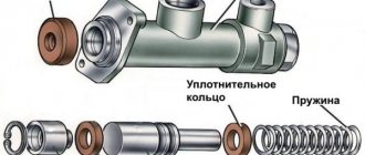
In the case of its use, the driver or machine operator, by pressing the pedal, transfers the force directly to the clutch fork by means of rods and cables. In the hydraulic version of the clutch, a piston with hydraulic fluid is also involved. As a rule, this option is used on heavy vehicles to facilitate the work of the driver. When using a hydraulic clutch actuator, the full travel of the pedal remains constant (this is ensured by the presence of a return spring on the clutch pedal). However, the value of its stroke changes, compensating for the decrease in the thickness of the driven disk as a result of wear: the smaller the thickness of the disk becomes, the greater, with the same full stroke of the clutch pedal, its stroke turns out to be greater, and the “higher” (closer to the end of the return stroke of the pedal when released) the clutch engages.
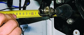
At the clutch pedal with a mechanical cable drive, the full travel is added as the driven disk wears out (the clutch pedal rises up relative to the floor level), along with this, its working stroke also increases. Pedal free play is set by adjusting the length of the cable. It is in the normal position of the order of 30 ... 40 mm.
By design, the clutch is electromagnetic, friction or hydraulic type. The friction version of the clutch provides the transmission of torque using friction. The clutch of the electromagnetic type is controlled by means of a magnetic field. In the hydraulic version of the clutch, the connection is provided by the flow of hydraulic fluid.
The clutch is electromagnetic if the compression of the driving and driven elements of the mechanism is carried out by means of electromagnetic forces. The electromagnetic clutch is permanently open. This rare type of clutch was installed on some modifications of machines with manual control. Between the driving and driven disks there was a ferromagnetic powder that did not interfere with the separate rotation of the shafts. But after applying an electric current to the electromagnet winding, the powder “hardened” and transmitted torque.
For heavy loads such as trucks and sports cars, a high friction ceramic clutch is also used, but it "grabs" sharply and is therefore unsuitable for use in standard cars.
The most common type is friction. Depending on the number of disks used, it can be single-disk, double-disk or multi-disk.
Types of clutch
dry clutch
The principle of operation of this type of clutch is based on the friction force arising from the interaction of dry surfaces: driving, driven and pressure disks. This provides a rigid connection between the engine and gearbox. Dry single-plate clutch is the most common type used on the bulk of cars with manual transmission.
Wet clutch
This type of clutch involves the operation of rubbing surfaces in an oil bath. Compared to dry, this scheme provides a smoother contact between the discs; the assembly is more efficiently cooled by fluid circulation and can transfer more torque to the transmission.
Wet double clutch
Wet scheme is usually used on modern dual-clutch robotic gearboxes. The peculiarity of the operation of such a clutch is that the even and odd gears of the gearbox are supplied with torque from separate driven disks. The clutch drive is hydraulic, electronically controlled. Gear shifting occurs with a constant transmission of torque to the transmission without breaking the power flow. This design is more expensive and difficult to manufacture.
Dry double disc clutch
Dry double-disk clutch involves the presence of two driven disks and an intermediate spacer between them. This scheme is able to transmit more torque with the same dimensions of the clutch mechanism. By itself, it is easier to manufacture compared to wet. Typically used on trucks and cars with particularly powerful engines.
Dual mass flywheel clutch
The dual mass flywheel consists of two parts. One of them is connected to the engine, the second - to the driven disk. Both components of the flywheel have a small free play relative to each other in the plane of rotation and are connected by springs to each other.
Diagram of a dual-mass flywheel
A special feature of the clutch of a dual-mass flywheel is the absence of a spring damper of torsional vibrations in the driven disk. The vibration damping function is built into the flywheel design. In addition to transmitting torque, it most effectively smooths out vibrations and loads arising from uneven engine operation.
Dry and wet clutch types
In addition, the clutch can be wet or dry. In the dry type of clutch, the discs work under conditions of dry friction. Wet clutch involves the operation of discs in liquid. The most common in modern vehicles is a dry single-plate clutch.
The wet clutch type (working in an oil bath) is now used mainly on motorcycles with a transverse engine. Since motorcycle power units have a common oil sump for both the motor and the gearbox. The clutch parts in them are combined with the engine transmission and engine start system, and they are lubricated with common engine oil. On automobiles, oil-bath clutches have practically fallen into disuse.
Double and multi-plate clutches
Vehicles with very powerful engines are equipped with a double-plate or multi-plate clutch. With the same dimensions, such clutch options transmit a significantly greater torque and provide a much longer resource for the entire structure. A spacer is located between the driven disks. The result is more friction surfaces. Double disc mechanisms are installed to increase the life of the clutch, due to the large power of the engines and the need to transmit increased torques.
Triple disc clutch for Nissan Skyline GT.
This is how it works. The release bearing presses the release levers, and they pull the pressure plate. The pressure plate moves away from the first driven and releases the release springs. They release the intermediate drive disk, and it moves away from the second friction disc due to other squeezing springs, just as much as the pressure one moved away from the first friction disc. During the reverse movement, the squeezing springs contribute to the uniform pressing of the intermediate disc to the second driven and the pressure disc to the first driven. The pressure plates move along the studs that are screwed into the flywheel, and the clutch basket is attached to them. The studs are fitted with compression springs.
Clutch with pneumatic booster
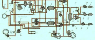
On heavy trucks with a large payload, for example, on MAZs, a clutch drive with a pneumatic booster is installed. Pneumatic reinforcement is designed to reduce the muscular effort applied to the clutch pedal.
The device is as follows: pedal, traction, spool (aka control valve), hoses, pneumatic chamber, levers, brake, input shaft with brake drum. Principle of operation: when the pedal is released, the inlet valve of the spool is closed, and the outlet valve is open. When you press the pedal, the force is transmitted through the rod and the spool to the clutch release fork. At the same time, the inlet valve opens in the spool and the outlet valve closes - the spool body moves towards the outlet valve, the outlet valve is pressed against the inlet valve and closes, and the inlet valve opens with this movement. Air through the intake valve enters the pneumatic chamber, which, due to air pressure, helps to press the clutch release fork.
Common clutch problems and their symptoms
- Incomplete engagement of the clutch (with “slip”) is a consequence of oiling or wear of the friction linings of the driven disk, broken springs, incorrect pedal stroke amplitude (its small free play). To eliminate this malfunction, it is necessary to replace the driven disk, eliminate scuffing on the disks, and inspect the drive for malfunctions. When “slippage” occurs, when the clutch pedal is fully released, the disks slip one relative to the other. From prolonged slipping, the discs begin to heat up significantly, the steel driven disc may warp, and the cast-iron flywheel and pressure (or pressure) discs may become cracked. Friction linings wear out and burn in an accelerated mode, and this burnt smell reaches the cabin. If not repaired, then the process gradually progresses, first at high, then at low speeds. Up to the point that it becomes impossible to even move off in first gear.
- Incomplete disengagement of the clutch (when the clutch “leads”) is a consequence of a large free play of the clutch, broken springs, a warped driven disk or an incorrectly installed pressure disk. It is also possible when the release levers are deformed; or the release bearing is sticking, does not move with the pressure clutch. It is possible that the clutch disc does not move along the splines (grease thickened or contaminated). To eliminate this malfunction, it is necessary to remove air from the hydraulic drive, adjust the free play of the pedal, replace inoperative discs and springs. Incomplete shutdown is manifested by crackling sounds of gears when shifting gears and, accordingly, leads to accelerated wear of gearbox parts.
- Jerks when engaging the clutch . When the car, despite the smooth release of the clutch pedal, starts “jerks”, this indicates the destruction of the friction linings, the warping of the driven disk, or the breakdown of the damper springs, or the wear of the friction washers. It is also possible that the driven disk seize when moving along the splines of the gearbox input shaft, as well as jamming of the pressure clutch or destruction of the release bearing.
- Malfunctions of the hydraulic drive system . If air enters the hydraulic clutch release actuator, the pedal may “fall through”, and as a result, the clutch may not be fully released. In this case, it is necessary to remove air bubbles with a part of the fluid (bleed the clutch), and add fresh. When the clutch does not disengage at all in cable-driven mechanisms, the cable may have broken. When the clutch pedal does not return to its original position, the return spring has been disconnected. If, when the clutch is disengaged, a strong noise is heard generated by the release bearing, then this indicates its wear.
If the clutch drive is mechanical (lever or cable), then as the friction linings wear out, the clutch pedal will gradually rise, and with a hydraulic drive, the pedal does not change its position, and the fluid level in the reservoir decreases.
So, the clutch mechanism plays a huge role in the functioning of any car or tractor. The technical condition of the entire vehicle largely depends on its serviceability and performance. Therefore, in order to ensure long and reliable operation of all elements of the clutch mechanism, it is important to use it smoothly, and without the need to practice excessively long pressing the pedal. Under such gentle operating conditions, the clutch will last a long time.
The principle of operation of the friction clutch
The operation of a dry single-disk friction clutch is very simple and boils down to the following. The clutch is constantly engaged - this is provided by a diaphragm spring (or a series of springs) that presses the pressure plate against the driven disk and against the flywheel. In this position, the entire clutch assembly rotates as a single unit, and the torque is fully transmitted to the gearbox.
When shifting gears, the clutch is disengaged: when you press the pedal, the spring is compressed (by means of the clutch actuator, pressure fork, clutch and release bearing), its plates, fixed in the “basket”, act as levers and take the pressure plate away from the driven disk. At this moment, the transmission of torque from the engine to the box stops and you can change gear.
After switching on the desired gear, the clutch pedal is released, the spring returns to its original position, pressing the pressure plate against the drive plate and the flywheel - the transmission of torque resumes.
However, the main advantage and all the possibilities of adhesion appear at the moment the car starts to move. The clutch is designed in such a way that the discs can be pressed against each other with different force, and therefore the transmission of torque can be carried out to the extent that it is necessary. If you slightly release the clutch pedal, then the discs will be pressed against each other weakly and slip, respectively, and the torque will not be completely transmitted to the box and wheels - this makes it possible to start and smooth acceleration of the car.
