Purpose and functions of the node
Water in district heating networks reaches a temperature of 150 ° C and moves along external lines at a pressure of 6-10 bar. Why are such high coolant parameters maintained:
- To ensure that high-temperature boilers or other thermal power equipment operate with maximum efficiency.
- To deliver heated water to areas remote from the boiler house or CHP, network pumps must create a decent pressure. Then, at the heat inputs of nearby buildings, the pressure reaches 10 bar (pressure testing - 12 bar).
- Transportation of superheated coolant is economically beneficial. A ton of water brought to 150 degrees contains much more thermal energy than a similar volume at 90 °C.
Reference. The coolant in the pipes does not turn into steam, since it is under pressure, which keeps water in a liquid state of aggregation.
The detail is simple - it looks like an ordinary tee with flanges
. According to the current regulatory documents, the temperature of the coolant supplied to the water heating system of a residential or office building should not exceed 95 ° C. Yes, and the pressure of 8-10 atmospheres is too high for an intra-house heating system. This means that the specified water parameters need to be adjusted downward.
An elevator is a non-volatile device that lowers the pressure and temperature of the incoming coolant by mixing in chilled water coming from the heating system. The element shown above in the photo is part of the heating unit circuit, it is installed between the supply and return pipelines.
The third function of the elevator is to circulate water in the house circuit (usually a one-pipe system). That is why this element is of interest - with external simplicity, it combines 3 devices - a pressure regulator, a mixing unit and a water jet circulation pump.
Elevator element with interchangeable nozzle
What is an elevator
To understand and understand what this element is, it is best to go down to the basement of the building and see with your own eyes. But if you have no desire to leave your home, then you can see the photo and video files in our gallery. In the basement, among the many valves, valves, pipelines, pressure gauges and thermometers, you will definitely find this unit.
We suggest that you first understand the principle of work. Hot coolant for heating systems is supplied to the building from the district boiler house, and cooled is discharged.
This requires:
- Supply pipeline - delivers hot coolant to the consumer;
- Return pipeline - performs the work of removing the cooled coolant and returning it to the district boiler house.
Typical diagram of an elevator heating unit
For several houses, and in some cases for each, if the houses are large, thermal chambers are equipped. In them, the coolant is distributed between the houses, and shut-off valves are installed, which serves to cut off pipelines. Also, drainage devices can be made in the chambers, which serve to empty pipes, for example, for repair work. Further, the process depends on the temperature of the coolant.
In our country, there are several basic modes of operation of district boiler houses:
- Supply 150 and return 70 degrees Celsius;
- Respectively 130 and 70;
- 95 and 70.
The choice of mode depends on the latitude of residence. So, for example, for Moscow, a 130/70 schedule will be enough, and for Irkutsk, a 150/70 schedule will be needed. The names of these modes have the numbers of the maximum load of pipelines. But depending on the air temperature outside the window, the boiler room can operate at temperatures of 70/54.
Knot in the basement
This is done so that there is no overheating in the rooms and that it is comfortable to be in them. This adjustment is carried out at the boiler room and is a representative of the central type of adjustment. An interesting fact is that in European countries another type of regulation is carried out - local. That is, there is an adjustment at the heat supply facility itself.
Heating networks and boiler houses in such cases operate at the maximum mode. It is worth saying that the highest performance of boiler units is achieved precisely at maximum loads. The coolant for heating systems comes to the consumer and is already locally regulated by special mechanisms.
These mechanisms are:
- Outdoor and indoor air temperature sensors;
- Servo;
- Actuator with valve.
Such systems are equipped with individual devices for metering thermal energy, due to this, great savings in financial resources are achieved. Compared to elevators, such systems are less reliable and durable.
So, if the coolant has a temperature of no more than 95 degrees, then the main task is the high-quality physical distribution of heat throughout the system. To achieve these goals, collectors and balancing valves are used.
Mudguard for the assembly that requires the instruction manual
But in the case when the temperature is above 95 degrees, then it needs to be slightly reduced. This is what elevators do in the heating system, they mix chilled water from the return to the supply pipeline.
Important. The process of adjusting the elevator assembly is the simplest and cheapest mechanism, the main thing is to correctly calculate the heating elevator.
Functions and characteristics
As we have already dealt with you, the elevator of the heating system is engaged in cooling superheated water to a predetermined value. Then this prepared water enters the radiators in each apartment.
This element improves the quality of the entire building system and, with proper installation and selection, performs two functions:
- Mixing;
- Circulation.
Advantages of the elevator heating system:
- Simplicity of design;
- High efficiency;
- No electrical connection required.
Flaws:
- We need an accurate and high-quality calculation and selection of a heating elevator;
- There is no possibility to regulate the outlet temperature;
- It is necessary to observe a pressure difference between supply and return in the region of 0.8-2 bar.
In our time, such elements have become widespread in the economy of thermal networks. This is due to their advantages, such as resistance to changes in hydraulic and temperature regimes. In addition, they do not require the constant presence of a person.
Components
Important. Calculation, selection and adjustment of elevators should not be done by hand, it is better to leave this matter to specialists, since a choice error can lead to big problems.
Design
The elevator consists of:
- rarefaction chambers;
- Nozzles;
- jet elevator.
Among heat engineers there is a concept as a strapping of the elevator assembly. It consists in installing the necessary shut-off valves, pressure gauges and thermometers. All this is assembled and is a node.
Important! To date, manufacturers are implementing elevators that are capable of adjusting the nozzle due to an electric drive. At the same time, it is possible to adjust the flow rate of the coolant in automatic mode. But it is also worth noting that such equipment is not yet distinguished by a high degree of reliability.
Approximate temperatures
The principle of operation of the elevator
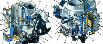
Outwardly, the design resembles a large tee made of metal pipes with connecting flanges at the ends. How the elevator is arranged inside:
- the left branch pipe (see the drawing) is a converging nozzle of the estimated diameter;
- behind the nozzle is a cylindrical mixing chamber;
- the lower branch pipe is used to connect the return line to the mixing chamber;
- the right branch pipe is an expanding diffuser that directs the coolant into the heating network of a multi-storey building.
In the drawing, the nozzle of the ejected flow is conventionally shown from above, although it is usually located below
Note. In the classical version, the elevator does not require connection to the house electrical network. An updated version of the product with an adjustable nozzle and an electric drive is connected to an external power source.
The steel elevator unit is connected by the left branch pipe to the supply line of the centralized heating network, the lower one - to the return pipeline. On both sides of the element, shut-off valves are placed, plus a strainer - a sump (otherwise - a sump) at the feed. The traditional scheme of a thermal substation with an elevator also includes pressure gauges, thermometers (on both lines) and an energy meter.
Now let's look at how the elevator jumper works:
- Superheated water from the heating network passes through the left branch pipe to the nozzle.
- At the moment of passing through the narrow section of the nozzle under high pressure, the flow is accelerated according to Bernoulli's law. The effect of a water jet pump begins to operate, which circulates the coolant in the system.
- In the area of the mixing chamber, the water pressure is reduced to normal.
- The jet moving at high speed into the diffuser creates a vacuum in the mixing chamber. An ejection effect occurs - a fluid flow with a higher pressure entrains the coolant returning from the heating network through the jumper.
- In the chamber of the heating elevator, the chilled water is mixed with superheated water, at the outlet of the diffuser we get the coolant of the required temperature (up to 95 ° C).
Clarification. It is worth noting that the elevator unit also uses the principle of injection in its work - mixing of two jets with simultaneous transfer of energy. The pressure of the resulting flow becomes less than the original, but more sucked from the return. The process is more clearly shown in the video:
The main condition for the normal operation of the elevator is a sufficient pressure drop between the main supply and the return line. The indicated difference should be enough to overcome the hydraulic resistance of house heating and the injector itself. Please note: the vertical jumper cuts into the return line at an angle of 45° for better separation of flows.
At the supply from the heating network, the pressure is the highest, at the outlet of the diffuser - medium, in the return line - the lowest. The same thing happens in the elevator with the water temperature.
Technological scheme of the elevator - show everything that is hidden
Blogs
Vladimir Poperechny
21 November 2021, 10:00
3427
I am sure that if not everyone, then many readers have come across the technological scheme of the elevator. Someone delved into the drawing, someone at the facility.
For an elevator, this is one of the main documents and one of the first drawings in a construction project. The technological scheme is analyzed by everyone - the customer, the equipment supplier, the expert, the builder.
The question is responsible - having built an elevator without understanding all possible flows, you may encounter an inability to perform a certain operation. Or vice versa, without understanding the possibility of changing routes in case of a breakdown, the elevator may stop altogether during the season.
But a seemingly simple task is to see if a couple of flows for two or three typical batches of grain is becoming more and more difficult every minute. You begin to “deep into” the technological scheme. You check the availability of certain streams, clarify (and often defend) the need for others.
The designer details the technological scheme with a diagram of the "main" production lines. But a cursory glance suggests that in addition to the main flows, there are also secondary ones, which, it turns out, are an order of magnitude larger than the main ones. Describe secondary flows. At the same time, you “keep in mind” the performance of the equipment. You are considering the simultaneous execution of several threads for different batches of grain (by culture, volume).
And here you understand that the theory about a person’s short-term memory about remembering a maximum of seven units is pure truth. And these units are far from being parallel streams, but units of equipment of one stream.
Analysis of circuit flows is the first step towards a more complete use of equipment, rational organization of work. Later you understand that it would be nice to “see” how this scheme works, how containers are filled, grain is being finalized. Experiment for different batches, with higher humidity for example. For small volumes, different speeds of unloading crops from bunkers and silos, etc. Correct the scheme and look again what happened. So to speak, to "balance" the technological scheme, or something.
And the result would be worthy - a reduction in electricity consumption, injury of grain, downtime of cars, wagons, ships. This is saving on unnecessary transport equipment, irrational capacities, reducing operating costs and increasing the operational capabilities of the elevator.
The frequent repetition of these calculations in itself, as it were, forced the development of simple software - an editor of technological schemes. Of course with functionality for analysis and modeling. Well, more precisely, start developing. Because there is no shortage in the desire for new functions.
In general, the program resembles a regular CAD editor. The user has the ability to build a technological scheme of the elevator by simply creating/drag and drop certain objects on the desktop of the program, connecting them with engineering networks (gravity, aspiration), setting the characteristics of the equipment (from the volume, productivity and length of the equipment, to the angle of inclination and transition sections of gravity flows) .
In addition to the ease of creating and editing a diagram, today we automatically calculate all elevator flows with characteristics (length of grain run in the flow, movement speed, performance critical points, power consumption, etc.), parallel operating flows, flows through equipment or gravity flows between equipment.
The program can automatically check the scheme for the presence of main flows, automatically generate drawings of production lines, specifications of technological equipment, explanatory notes.
At the testing stage, the module for the operational calculation of the operation of the elevator according to various plans for the receipt, storage and shipment of grain.
Vladimir Poperechny
Specifications for standard products
The line of factory-made elevators consists of 7 standard sizes, each is assigned a number. When selecting, 2 main parameters are taken into account - the diameter of the neck (mixing chamber) and the working nozzle. The latter is a removable cone, which changes if necessary.
The dimensions of the constituent elements of the product, see the table below.
The nozzle is replaced in two cases:
- When the flow area of the part increases as a result of natural wear. The reason for the development is the friction of abrasive particles contained in the coolant.
- If it is necessary to change the mixing ratio, increase or decrease the temperature of the water supplied to the house heating system.
The numbers of standard elevators and the main dimensions are given in the table (compare with the designations on the drawing).
Please note: the technical specifications do not indicate the nozzle flow area, since this diameter is calculated separately. To select the number of the finished elevator tee for a specific heating system, it is also necessary to calculate the required size of the mixing-injection chamber.
Calculation and selection of the elevator by number
Let us immediately clarify the procedure: first of all, the diameter of the mixing chamber is calculated and the appropriate elevator number is selected, then the size of the working nozzle is determined. The diameter of the injection chamber (in centimeters) is calculated using the formula:
The indicator Gpr participating in the formula is the actual flow rate of the coolant in the system of an apartment building, taking into account its hydraulic resistance. The value is calculated like this:
- Q is the amount of heat consumed to heat the building, kcal/h;
- Tcm is the temperature of the mixture at the outlet of the elevator tee;
- T2o - water temperature in the return line;
- h is the resistance of the entire heating distribution, together with radiators, expressed in meters of water column.
Reference. To insert incomprehensible kilocalories into the formula, you need to multiply familiar watts by a factor of 0.86. Water column meters are converted to more common units: 10.2 m of water. Art. = 1 bar.
Elevator number selection example. We found out that the real consumption Gpr will be 10 tons of mixed water in 1 hour. Then the diameter of the mixing chamber is 0.874 √10 = 2.76 cm. It is logical to take mixer No. 4 with a 30 mm chamber.
Now we find out the diameter of the narrow part of the nozzle (in millimeters) using the following formula:
- Dr is the previously determined size of the injection chamber, cm;
- u is the mixing ratio;
- Gpr - our consumption of the finished coolant at the supply to the system.
Although outwardly the formula seems cumbersome, in reality the calculations are not too complicated. One parameter remains unknown - the injection coefficient, calculated as follows:
We have deciphered all the designations from this formula, except for the parameter T1 - the temperature of hot water at the inlet to the elevator. If we assume that its value is 150 degrees, and the supply and return temperatures are 90 and 70 °C, respectively, the desired Dc size will be 8.5 mm (at a flow rate of 10 t/h of water).
When the value of the pressure Hp at the entrance to the elevator from the side of the main is known, an alternative formula for determining the diameter can be used:
Comment. The result of the calculation according to the last formula is expressed in centimeters.
Elevator equipment
The grain processing and storage complex consists of a number of technologically linked facilities, the totality of which may differ fundamentally depending on the purpose of the complex: an elevator, a mill, a feed mill, a groats mill, an oil mill. A modern elevator consists of a set of grain storage equipment (metal containers) and transport equipment (bucket elevators and conveyors). Metal elevators are equipped with temperature control and aeration systems. A modern elevator necessarily includes a laboratory and weighing equipment to control the quality and quantity of incoming and outgoing grain. In such an elevator, the grain improves its quality after drying and cleaning from impurities.
As a rule, the complex consists of the following objects:
- Point of acceptance of grain from vehicles , consisting of an auto-tipper, a receiving hopper (a pit), conveyors and bucket elevators, a dust aspiration system. Designed for receiving grain from vehicles with a trailer up to 18 m long and with a carrying capacity of 60 tons. Depending on the performance and technological scheme of the complex, such a point is designed for 1, 2 or more passages. The performance of the acceptance point for one passage is determined by the technological time of unloading one car (arrival-departure time, opening-closing of the sides, lifting-lowering the auto-tipper) and usually amounts to 100-120 t/h.
- The working tower , in which the cleaning equipment is located, is the main technological and most important structure of the elevator. It is intended for the delivery of grain coming from receiving devices, its cleaning and distribution to containers or other facilities of the complex. Structurally, the working tower is a multi-storey structure based on a powerful steel frame sheathed with profiled galvanized sheets. The tower contains cleaning equipment (scalpers, separators), bucket elevators (at least three) for lifting grain to the upper galleries, cleaning and shipping, an aspiration system, bunker (in-line) scales.
— The computer-controlled modern vacuum grain dryer is able to operate in automatic mode, maintaining a uniform predetermined moisture content of the grain at the exit from the dryer due to the use of the latest advanced drying technologies.
– Metal grain storage tanks (silos) installed on concrete bases with different capacities from 100 to 10,000 tons, arranged in a row or in another way, depending on their number and technological scheme. In turn, the tanks are divided into silos with a flat concrete base and silos with a conical metal bottom. To ventilate grain in silos with a flat base, special channels are provided, and in silos with a cone bottom, a special active ventilation system is installed. The tanks are structurally linked to the upper and lower galleries. The upper galleries consist of steel structures supported by silo stanchions and roofs, on which silo loading conveyors and maintenance aisles are located. The lower galleries, as a rule, are made in the form of reinforced concrete tunnels with a height of at least 2 m in the foundations of silos and are designed to accommodate conveyors for unloading containers.
— A device for receiving and unloading grain into railway wagons , which allows unloading 1, 2, or more wagons at the same time. It has a covered ground structure and an underground part, which houses transport equipment. To prevent the formation of dust during unloading/loading of wagons, a special aspiration system is installed.
– The laboratory , which has at its disposal automatic samplers and equipment for express analysis of incoming grain, determines various quality indicators of grain in a matter of seconds. Usually located in the same building with the administration of the elevator.
– The weighing complex , consisting of automobile (20 m long) and wagon electronic scales, is designed to determine the amount of received and released grain.
What are the advantages of having your own elevator?
Savings on grain transportation . The choice of the optimal location of the elevator several times reduces the cost of transporting grain to the place of storage and further shipment to consumers.
Accuracy of measurements. Modern tensometric scales are installed in the elevator. The owner receives information on the computer about the receipt and availability of grain in real time. This makes it possible to avoid "errors" in measuring weight, contamination, moisture, gluten, which is often the fault of unscrupulous elevators. Level sensors located in each silo allow you to get information about the amount of grain at any time. Weight accounting, together with automation, makes it possible to receive information on the receipt and availability of grain in real time, to prevent attempts at theft.
Quality control. Analysis of the qualitative characteristics of grain (nature, moisture, contamination, gluten) using automatic samplers and electronic equipment for express analysis with data entered into a computer.
Savings on drying and grain cleaning. The use of modern economical dryers and grain cleaning equipment reduces the cost of cleaning and drying grain.
Efficiency. The use of high-performance equipment makes it possible to take large volumes of grain for storage in a short time during the season and ship them by rail and road to the consumer. In the off-season, you can get additional profit by trading grain from other regions.
Low costs for storage of grain without loss of its quality . The emerging centers of grain self-heating are detected using a thermometry system and eliminated by active ventilation in silos, and grain transfer from silo to silo. The transfer of grain from silo to silo can be combined with the treatment of grain with pesticides. Only a few people serve the complex for receiving, cleaning, drying, storing and shipping grain.
Getting the maximum profit. According to the experience of recent years, grain prices increase by 1.5-2 times by spring. With your own modern elevator, you will save grain at minimal cost, without compromising quality, and get maximum profit.