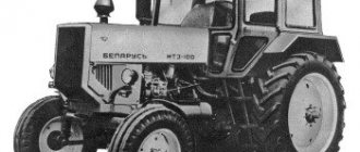
How does the electric torch heater MTZ-82 work?
Electric torch heater MTZ-82: What is it for and how does it work?
Scheme of the EFP device. To heat up the air and start the diesel engine D - 240, 243, there is a special device - an electric torch heater MTZ - EFP, which is installed directly in the tractor intake manifold.
This heater does not require any targeted maintenance and special settings, because its initial (factory) adjustment of switching on, as well as the gap between the core and the fitting, are set by the manufacturer.
However, it is still necessary to monitor it during the operation of the Belarusian tractor, checking the strength of the fasteners, electrical wiring, fuel pipeline and, if necessary, clean the jet in the fitting.
Operating principle
Thanks to the electric current from the accumulator battery, which is supplied to the coil and the electromagnetic coil, the heater is turned on by one toggle switch together with the starter.
In one position, electricity from the battery enters the spiral and reduces the voltage to 10 V, and in the other position, an electromagnetic coil is connected. The control element is located on the instrument panel of the tractor itself, and the entire warm-up takes no more than 15-20 seconds, keeping the temperature around 950 degrees.
The electromagnetic coil selects the armature, which is also a valve, and fuel enters through the hole formed, falling on a white-hot coil, where it ignites, allowing the diesel to start.
In the course of starting the diesel engine D - 240, 243, the fuel is delivered by a special pumping pump, and the direct supply is carried out by a separate dispenser, consisting of a triple felt disk clamped with a retaining nut. Thus, the level of fuel delivered through the dispenser in total does not exceed 12 cubic meters. cm per minute.
As soon as the diesel engine D - 240, 243 starts, the electromagnetic coil is disconnected from the battery power together with the starter, the anchor valve returns to its original position with the help of a spring, closing the hole through which fuel was supplied to the hot coil, and the operation of the electric torch heater immediately ends my job.
Scheme EFP-8101/500 of the MTZ-80, MTZ-82 tractor:
1 - fitting bolt; 2 - valve body; 3 - current-carrying terminals; 4 - fitting; 5 - electromagnetic coil; b - spring; 7 - anchor with ball valve; 8 - jet; 9 - incandescent spiral; 10 - casing.
Tips & Tricks
As mentioned at the beginning of the article, adjustment of the electric torch heater is not needed, but constant maintenance is required, especially if you take tractor operation seriously in winter.
It is not difficult to guess how many parts of the motor are spoiled during the spring-summer-autumn period, and therefore a good cleaning is simply necessary. Without fail (with the onset of cold), rinse the tank, jet and pipeline with some kind of non-freezing solution so that there are no malfunctions in the operation of the EFP and you do not have to use ether, for example, or some kind of blowtorches to start the engine, because the ether has a decent destructive impact, and from the lamps there is simply less sense.
1 - fitting bolt; 2 - fuel tube; 3 - fitting; 4 - valve spring; 5 - valve; 6 - body; 7 - filter; 8 - jet; 9 - housing with a coil; 10 - filament spiral.
Scheme of connecting the heater to the engine d 245
An electric torch heater is installed in the intake manifold and is necessary for air heating in order to facilitate diesel start-up. The electric current from the battery is supplied separately to the coil (Fig. 113) of the electromagnet and to the spiral. The heater is put into operation by the same switch as the starter.
In the first position of the switch, the current enters the filament circuit and causes a voltage drop of 10 V on it (together with the control element PD50-V and additional resistance SE50-V connected in series). The control element and additional resistance are located on the instrument panel of the tractor. Heating of the spiral to a temperature of approximately 950 °C occurs in 15–20 s.
Promotional offers based on your interests:
Rice. 113. Starting electric torch heater: 1 - fitting bolt; 2 - dosing element; 3 - nut; 4 - current-carrying terminal of the spiral; 5 - fitting; 6 - bypass valve spring; 7 - electromagnet coil; 8 - valve; 9 - valve body; 10 - spiral; 11 - casing; 12 - current-carrying terminal of the electromagnet coil.
In the second position of the switch, simultaneously with the starter, the electromagnet coil is included in the current circuit. In this case, the heater coil remains on, and the control element and additional resistance are shunted, but the voltage on the coil remains within the same limits due to the voltage drop on the starter.
The electromagnet coil draws in an armature connected to the valve; through the opened hole, fuel flows out of the valve body, falls on a hot spiral and ignites. Further, in the process of starting the diesel engine, fuel is supplied by the booster pump of the fuel pump.
Fuel supply (no more than 12 cm3/min) is provided by means of a metering element, which consists of three felt discs pressed with a nut. After starting the diesel engine, simultaneously with the automatic shutdown of the starter (the PC502 relay is de-energized), the electromagnet coil also loses power. The armature under the action of the spring moves to its original position, closes the hole in the valve body, stopping the fuel supply to the coil.
When the starter is turned off, the filament circuit is interrupted: the operation of the heater stops completely.
With the return of the VK-316B switch key to its original position, the current supply to the incandescent spiral is also stopped, i.e., the heater is de-energized.
Special maintenance of the electric torch heater is not required.
During operation, it is necessary to periodically check the reliability of fastening of both the heater itself and the electrical wiring and fuel line. If necessary, clean the jet hole in the fitting bolt.
The moment of turning on the heater and the gap between the core and the fitting are adjusted at the factory, and their additional adjustment during operation is not required.
Source
Engine preheaters MTZ 82(80)
The task of the pre-heating equipment is to stimulate the start of the engine in cold weather. Preheating is especially important for diesel engines due to high compression ratios requiring high rotational forces, as well as creating optimal temperature conditions for igniting the fuel in the combustion chambers. Depending on the method of heating, in addition to stimulating a quick start, the devices can provide general heating of the cylinder group and parts of the crank mechanism of the engine, which ensures a soft start, eliminating increased wear of the cold mechanism.
Electric torch heater MTZ 82
The device is standard equipment in the configuration of the MTZ 82(80) start-up system, which ensures the start of a diesel engine in the cold season. The function is the pre-heating of the intake air into the diesel cylinders, which ensures easy ignition when the combustible mixture is compressed in the combustion chambers.
The heater is installed in the branch pipe of the suction manifold D 240. The principle of operation is to heat the air by burning diesel fuel ignited by the heating coil of the device, the electrical supply of which is carried out from the tractor's standard electrical network.
Heater operation
The device is turned on by a separate key on the panel, the heater control is interlocked with key 12 (in the diagram) for controlling the starter. When the key is turned to the first position, an electric current of 17-22 A flows through a separate terminal to the heater coil, which heats up to 950 ° C for 25-30 seconds. The voltage in the network during heating drops to 10 volts. 11 connected in series to the circuit and additional resistance SE50-V 10 on the control panel, which, when ready to start, signals by flashing. In the second position, additional electricity is supplied through the second terminal of the device to the coil 6 for controlling the supply valve 7 . The electromagnetic field of the coil, overcoming the force of the return spring, opens the valve and passes diesel fuel to the hot coil 3 , where combustion occurs. Simultaneously with the rotation of the diesel engine by a working starter, heated air enters the cylinders.
Fuel is supplied to the device through a separate fuel line, from the fine filter of the tractor fuel system, by the pressure created by the booster pump of the high-pressure fuel pump during the starting rotation of the diesel engine or in other designs from a separate supply fuel barrel. After starting the diesel engine and automatic operation of the relay, simultaneously with the starter, the electric torch device is disconnected from the network. The supply valve automatically closes the passage of fuel to the coil by the force of the return spring. The device key on the panel after start-up is set to the “off” position.
The fuel supply (12 cmᶾ per minute) is regulated by a bolt and a metering fitting, which includes three felt disks TECH-4 (GOST 11025-64) tightened with a nut.
Advantages and disadvantages
The undoubted advantage is the autonomy of the device, the operation of which does not depend on external power sources. The reliability of the heater and the successful start of the diesel engine depend on the degree of charge and those. the state of standard batteries, which is often imperfect in practice. The short-term heating of the intake air during start-up stimulates the ignition of the fuel, however, does not provide heating of the entire engine parts. Therefore, at low temperatures, the start of a diesel engine is characterized by hard work until it is completely warmed up, which negatively affects the wear of rubbing surfaces in the unit, reducing its resource.
In addition, the appearance of soot on the valve of the device causes a loose overlap of the fuel, which, when flowing into the intake manifold, provokes detonation in a running engine, accompanied by incomplete combustion. Therefore, you need to pay attention to the correct operation of the valve. For insurance, you can install a valve on the fuel supply line to prevent fuel from entering when the diesel engine is running. In general, the device, of course, creates the conditions for a quick start in cold weather, but its use at temperatures below -10 ° C is desirable to accompany the preheating of the coolant.
Electric torch device KAMAZ
The electric torch device (EFD) is designed to facilitate the start of a cold engine at an ambient temperature below minus 5 ° C. The use of EFU is effective at ambient temperatures down to minus 22 ° C; at lower temperatures, a starting preheater should be used.
The principle of operation of the EFU is based on heating the air entering the engine cylinders with a torch of candles. The fuel supplied to the candle does not burn completely. The unburned part of it in the form of vapors and heated gas enters the cylinders, contributing to the emergence of additional ignition centers in the combustion chamber. Flare candles are connected to the low-pressure line of the engine fuel supply system at the site of the fine fuel filter - high-pressure fuel pump.
When the engine is started, the fuel priming pump supplies fuel through the fine filter 17 (Fig. 35) to the spark plugs 13. The bypass valve of the injection pump and the jet valve of the fine fuel filter are closed and fuel under pressure enters the EFU spark plugs with a minimum delay from the opening of the solenoid valve 11 At a pressure greater than 25 ... 45 kPa (0.25 ... 0.45 kgf / cm2), the jet valve opens, maintaining the optimum pressure in front of the EFU spark plug jet for stable flame burning.
The strength of the current consumed by the EFU does not adversely affect the subsequent starter discharge of the batteries. At the same time, the current consumed by the starter is reduced by 4-6 times due to earlier flashes in the engine cylinders.
When the EFU button is turned on, the voltage from the batteries through the EFU switch-on relay and the thermal relay is supplied to the torch candles. Simultaneously with the heating of the candles, the thermal relay heats up and activates, including the solenoid valve and the signaling device in the signaling device block. At the same time, the valve opens and fuel flows to the candles, and the signaling device lights up indicating that the device is ready to start the engine.
In addition, when the EFU button is turned on, voltage is applied to the relay, which breaks the circuit of the generator excitation winding, which is necessary to protect the spark plugs from the voltage generated by the generator when the engine reaches a stable mode is accompanied by the operation of the EFU. Preservation of the torch at a low speed of the crankshaft of the engine after start-up contributes to its rapid exit to an independent mode of operation and a decrease in the smoke that occurs in an unheated engine.
The resistance of the thermal relay coil is chosen so that a voltage of 19 V is provided at the plug outputs (the nominal voltage of the plug).
When the engine is started by the instrument and starter switch, the starter is turned on through an additional relay. At the same time, a relay is activated, the contacts of which shunt the thermal relay, that is, voltage is applied to the outputs of the candles, bypassing the thermal relay coil, since when the engine crankshaft is turned by the starter, the battery voltage decreases.
In order to avoid an increase in voltage on the candles after starting the engine, during the operation of the EFU, it is also provided to turn off the excitation winding of the generator.
- Maintenance and repair of electric torch device
Engine heating mtz 82 from 220 volts
Practice has shown that a heated diesel engine above 50 ° C starts up in conditions of any low ambient temperature, with serviceable and adjusted fuel equipment, without any problems. This is due to a decrease in resistance to rotation in the structural axes of the crank mechanism and the movement of parts in the diesel cylinders, as well as a sufficiently comfortable temperature for fuel ignition in the combustion chambers. Starting a warm engine provides instant lubrication to the parts, which ensures a soft start and the safety of the unit's resource.
Electric torch heater for D-245 diesel of MTZ-100 and MTZ-102 tractors
H
In order to heat the air and facilitate the start of the diesel engine, an electric torch diesel heater D-245 of the MTZ-100 and MTZ-102 tractors is installed in the suction manifold. From the storage battery, electric current is supplied separately to the electromagnet coil (7) and to the spiral (10) [Fig. 1]. The heater is put into operation by the same switch as the starter.
Rice. 1. Prestarting electric torch heater for D-245 diesel of MTZ-100 and MTZ-102 tractors.
1) - Bolt fitting;
Electric torch device
The electric torch device (EFD) is designed to facilitate starting a cold engine at negative ambient temperatures down to -25°C.
The principle of operation of the EFU is based on heating the air entering the engine cylinders with a torch of a candle flame. The fuel supplied to the candle does not burn completely. The unburned part of it in the form of vapors and gas enters the engine cylinders, contributing to the emergence of additional ignition sources in the combustion chamber. Flare candles are connected to the low pressure line of the engine fuel supply system in the area: fuel fine filter - high pressure fuel pump.
When starting the KAMAZ-740 engine, the low-pressure fuel priming pump 10 operates (Fig. 8.2) and the fuel, passing through the fine filter 18, is pumped to the spark plugs 16. The bypass valve of the high-pressure fuel pump and the jet valve of the fine fuel filter block the drain fuel lines 17 and 20 and provide fuel under pressure to the spark plugs with a minimum time delay from the opening of the solenoid valve. The electrical circuit of the EFU works as follows. When the device is turned on with the button on the instrument panel, the voltage from the batteries through the ammeter, relay and thermal relay is supplied to the torch candles and they are heated. Simultaneously with the heating of the candles, the thermal relay heats up and activates, including the solenoid valve and the control lamp. In this case, the valve opens fuel access to the candles, and the control lamp lights up indicating that the device is ready to start the engine.
In addition, when the EFU is turned on, voltage is applied to the relay, which breaks the circuit of the generator excitation winding. This is necessary to protect the spark plugs from the voltage generated by the generator when the engine's output to a stable mode is accompanied by the operation of the EFU. Preservation of the torch at a low speed of the engine crankshaft after start-up contributes to its rapid exit to an independent mode of operation and a decrease in pressure.
The current consumed by the EFU does not exceed 24 A. This amount of current consumed does not adversely affect the subsequent starter discharge of the battery.
9.3. Possible malfunctions of the engine start-up system at low temperatures, causes, symptoms and remedies
Electric torch heater of MTZ tractor
The electric torch heater is installed in the intake manifold and serves to heat the air in order to facilitate the engine start. The main components of the heater are: a housing with an electromagnet coil, a valve assembly and an incandescent spiral.
Electric current from the battery is supplied separately to the coil of the electromagnet and the spiral. The heater is switched on by the same VK316-B switch as the starter. When the switch is turned on in the first position, current is supplied to the filament circuit through the control element PD-50-V and additional resistance SE50-V21. In this case, the current on the spiral reaches 17-22 A, and the voltage is 10 V.
Warm up the coil for 30-35 s. After this time, the temperature of the coil reaches approximately 950 ° C. When the VK316-B switch is turned on in the second position, the electromagnet coil is turned on simultaneously with the starter. In this case, the heater coil remains switched on, while the control element and the additional resistance are shunted.
When current passes through the electromagnet coil, the armature placed inside it and serving simultaneously as a valve moves upwards, opening a hole through which fuel flows out of the valve body onto a hot spiral and ignites. With the start of cranking the engine crankshaft, fuel is supplied by the booster pump of the fuel pump.
Permissible fuel consumption (no more than 12 cm3/min) is ensured by installing a dosing element in the fitting bolt. After starting the engine, simultaneously with the automatic shutdown of the starter (the PC502 relay is de-energized), the power is turned off from the electromagnet coil and the armature moves to its original position under the action of the spring, blocking the hole in the valve body. The fuel supply to the coil is stopped. With the return of the VK316-B switch key to its original off position, the current supply to the filament spiral is also stopped - the heater is completely de-energized. Starting electric torch heater : 1 - fitting bolt; 2 - fuel tube; 3 - fitting; 4 - valve spring; 5 - valve; 6 - valve body; 7 - filter; 8 - jet; 9 - housing with a coil; 10 - filament spiral.
Components of the MTZ heater
The system includes two candles.
MTZ parts are screwed into the threaded holes of the tractor motor manifolds. Connect to the low pressure line.
Candles consist of the following components:
- A heating element;
- casing;
- Frame;
- Fuel filter;
- Screen;
- Fuel jet;
- Spiral;
- A tube;
- Net;
- Screw.
Fuel is supplied to the electric torch candles when the tractor engine is started by means of a booster pump through a special fine filter. The valves block the drain fuel lines.
This ensures the minimum delay time when supplying fuel. In addition to candles, the MTZ heater includes:
- Valve;
- Resistor;
- Switching relay;
- Control lamp;
- Switch;
- Winding relay.
Operating principle
The operation of the electric torch heater is divided into three stages:
- Before starting the engine;
- At the time of launch;
- After launch.
Inside the housing there is a valve and an electromagnet winding.
Fuel flows from the tank through a hollow bolt.
In the lower part, an incandescent spiral with a casing having several holes is fixed.
The MTZ heater is started by the same switch as the starter. The lever is turned to the first position.
The current comes to the spiral through the control element and through the additional resistance. It is located in the cockpit. The spiral heats up in twenty seconds to a temperature of 950 degrees.
When the switch is turned to the second position, the electromagnet is turned on along with the starter. The spiral is also involved. The resistance and control element are switched off.
When current passes through the coil, the valve moves up. A hole is opened for the supply of fuel from the body to the hot spiral. Ignition occurs. The air passing through the pipeline is warmed up.
When starting a diesel engine of a modern tractor, the starter is turned off and the coil is de-energized. The valve is pushed down by a spring. The hole is covered.
The fuel supply stops.
