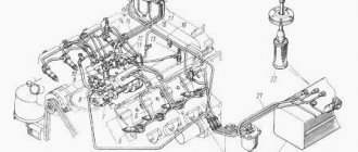
Schematic diagram of the fuel supply system of a diesel engine with a single-plunger injection pump
A schematic diagram of a diesel fuel supply system with a single-plunger distribution fuel pump (TNFP) with a plunger cam end drive is shown in the figure:
Rice. Schematic diagram of the fuel supply system of a diesel engine with a single-plunger injection pump: 1 - low pressure fuel line; 2 - thrust; 3 – a pedal of giving of fuel; 4 - injection pump; 5 - solenoid valve; 6 - high pressure fuel line; 7 - fuel line drain line; 8 - nozzle; 9 - glow plug; 10 - fuel filter; 11 – fuel tank; 12 - fuel priming pump (used for long lines; 13 - battery; 14 - ignition lock; 15 - control unit for the time of switching on glow plugs
Fuel from tank 11 is pumped through the low-pressure fuel line to the fine fuel filter 10, from where it is sucked in by the low-pressure fuel pump and then sent to the internal cavity of the high-pressure fuel pump housing 4, where a pressure of about 0.2 ... 0.7 MPa is created. Further, the fuel enters the high-pressure pumping section and, using a plunger-distributor, in accordance with the order of operation of the cylinders, is supplied through the high-pressure fuel lines 6 to the injectors 8, as a result of which the fuel is injected into the diesel combustion chamber. Excess fuel from the injection pump housing, injector and fuel filter (in some designs) is drained through fuel lines 7 back into the fuel tank. Cooling and lubrication of the injection pump are carried out by the fuel circulating in the system. The fuel fine filter is essential for the normal and trouble-free operation of the injection pump and injector. Since the plunger, sleeve, discharge valve and nozzle elements are precision parts, the fuel filter must retain the smallest abrasive particles 3 ... 5 microns in size. An important function of the filter is also the retention and sedimentation of water contained in the fuel. Moisture ingress into the interior of the pump can lead to failure of the latter due to corrosion.
The fuel pump delivers a strictly metered amount of fuel under high pressure to the diesel cylinders at a certain point in time, depending on the load and speed, so the characteristics of the engines depend significantly on the operation of the high-pressure fuel pump.
The basic principles of installing a high-pressure fuel pump on KamAZ and setting the injection moment
The need to control the moment of injection arises for drivers of Euro 2 and Euro 3 KamAZ trucks.
There are situations when the plates broke off on the way outside the city. But how to be and what to do, we will consider the details further.
The moment of injection - the meaning of the process
The moment of injection is the beginning of the supply of fuel at the moment when the valve reaches its maximum upper point with the intake and exhaust pistons closed. As a result, the piston compresses the air as much as possible, which means that fuel can be supplied.
Adjustment of this process is necessary for the following reasons.
- For each power unit, this period is different.
- The difference in fuel, for example, winter and summer diesel fuel.
For ease of adjustment, each engine has corresponding marks and degrees. If you set the injection moment strictly according to the indicated values, then KamAZ will behave properly, provided that the engine is calibrated, the high-pressure fuel pump and GOST fuel.
How to put injection pump on KamAZ? The drive is installed on the key on the gearbox side. The coupling can be rotated 180 degrees in two directions. If the actuator clamping screw is located at the top, then the mark on the pump and coupling must be opposite each other.
Having installed everything as expected, you can start the engine. If it so happened that the activation of the engine was not completed, and thick white smoke was pouring out of the exhaust pipe, then this means that they were confused by 180 degrees. You can solve the problem by turning the clutch in the other direction.
Reference! If it turned out that there are several marks on the coupling, it is recommended to put it approximately in the middle of the adjustment slots.
Scheme and general view of the distribution pump VE
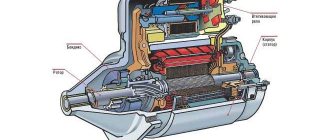
The diagram of the distribution pump VE is shown in the first figure, and its general view is in the following.
The main functional blocks of the VE fuel pump are:
- low pressure rotary vane fuel pump with control bypass valve
- high pressure unit with distributor head and dosing sleeve
- automatic speed controller with a system of levers and springs
- solenoid shut-off valve that cuts off the fuel supply
- automatic device (automatic) for changing the fuel injection advance angle
Rice. Fuel pump diagram - Bosch VE: 1 - pump drive shaft; 2 - bypass valve for internal pressure regulation; 3 – fuel supply control lever; 4 – regulator weights; 5 - fuel drain jet; 6 - full load adjustment screw; 7 - regulator transfer lever; 8 - solenoid valve for stopping the engine; 9 - plunger 10 - central plug; 11 - discharge valve; 12 - dosing clutch; 13 - cam disc; 14 - automatic fuel injection advance; 15 - roller; 16 - clutch; 17 - low pressure fuel priming pump
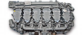
Rice. General view of the distribution high pressure fuel pump VE: a - high pressure fuel pump; b - high-pressure block with a distribution head and a dosing sleeve. The positions correspond to the positions in the previous figure.
Video of adjusting the fuel pump KAMAZ
Installation of high pressure fuel pump and ignition adjustment KAMAZ
How to add, reduce fuel on the injection pump KAMAZ
KAMAZ 55111 I set the ignition and a little about the clutch
Repair of injection pump KAMAZ
After adjusting the injection pump KAMAZ
How to add traction on KAMAZ.
Super ignition unit (OVT) of KamAZ and MTZ, which has no analogues in the world.
Checking the pressure of plunger pairs. KAMAZ (YAZDA).
How to make economical KAMAZ
Starting regulator 003.AVI
TECHNOLOGICAL CARD No. 2. 5.
TESTING AND ADJUSTING THE HIGH PRESSURE FUEL PUMP (TNVD) OF THE KAMAZ-740 ENGINE
Total labor intensity - 235.0 people. min.
Contractor - mechanic for the repair of fuel equipment of the 5th category
EQUIPMENT, DEVICES, TOOLS
Bench for testing fuel pumps Minor-8B, NTs-128 or STAR-12F; stopwatch SM-60 GOST 5072-72; caliper ShTs-1-125-0.1 GOST 166-80; dynamometer 06-8790-4017; air dispenser S-413; tool for removing and installing automatic injection advance clutch I 801.16.000; special wrench for unscrewing the fastening nut of the automatic clutch; open wrenches 10.17 mm GOST 2839-80; combined pliers GOST 17438-72; measuring container for oil filling; measuring container for fuel PREPARATORY WORKS Labor intensity -11.0 pers. min.
1. Install the injection pump on the stand. High pressure fuel pump can also be adjusted on the stands: MTs-104 (Czechoslovak) MD-12 (Hungarian production); A1027 (Austrian), etc. (Stand STAR-12).
2. Fill the pump with oil. Oil M10G2K GOST 8581-78 in a volume of 0.16 liters to the level of the drain hole on the rear cover of the regulator. (Capacity measured).
3. Install a plug instead of bypass valve 27-32 (Fig. 1). (Wrench 17 mm).
4. Connect the fuel supply line to screw 21 of the pump housing. (Wrench 17 mm).
5. Connect the drain pipes to fittings 48 of the injection pump.
6. Set the rail to the position corresponding to the off fuel supply.
7. Remove the automatic fuel injection advance clutch.
CHECKING AND ADJUSTING THE START OF THE FUEL SUPPLY OF THE KAMAZ-740 ENGINE
Labor intensity - 8.0 people. min.
8. Check the order of alternation of the beginning of the fuel supply according to the angle of rotation of the camshaft. The start of fuel delivery by the pump sections is determined by the angle of rotation of the pump camshaft when it is rotated clockwise, when viewed from the drive side. The first section of a correctly adjusted pump begins to supply fuel 42°30' ±30' before the axis of symmetry of the cam profile. At the moment when the eighth section of the pump starts supplying fuel, the marks on the pump housing and the driven coupling half must match. Mismatch of marks ±0.5 mm.
If the angle at which fuel supply by the eighth section begins is conventionally taken as 0°, then
The discrepancy between the indicators between the beginning of the fuel supply by any section of the pump relative to the first is allowed no more than 20'. The adjustment is made by installing a certain thickness of the heel of the pusher 64 under the plunger 61. A change in its thickness by 0.05 mm corresponds to 12' of the angle of rotation of the camshaft. When installing a heel of a larger thickness, the fuel starts to be supplied earlier, a smaller one - later. Check the tightness of the discharge valves.
Additional devices of distribution injection pump VE
The distribution injection pump VE can also be equipped with various additional devices, for example, fuel supply correctors or a cold start accelerator, which allow you to individually adapt the injection pump to the features of this diesel engine.
The drive shaft 1 of the fuel pump is located inside the injection pump housing, the rotor 17 of the low-pressure fuel pump and the drive gear of the regulator shaft with weights 4 are installed on the shaft. The injection pump is carried out from the diesel crankshaft, gear or belt drive. In four-stroke engines, the high-pressure fuel pump shaft speed is half the crankshaft speed, and the distribution high-pressure fuel pump operates in such a way that the translational movement of the plunger is synchronized with the movement of the pistons in the diesel cylinders, and the rotational movement ensures the distribution of fuel over the cylinders. The translational movement is provided by the cam washer, and the rotational movement is provided by the fuel pump shaft.
The automatic speed controller includes centrifugal weights 4, which act on the metering clutch 12 through the regulator clutch and a system of levers, thus changing the amount of fuel supply depending on the speed and load modes of the diesel engine. The high-pressure fuel pump housing is closed from above by a cover in which the axis of the control lever connected to the accelerator pedal is installed.
The fuel injection advance automatic device is a hydraulic device, the operation of which is determined by the fuel pressure in the internal cavity of the injection pump, created by a low-pressure fuel pump with a control bypass valve 2.
to the entry “Device injection pump BOSCH (Bosch) VE. High pressure fuel pump”
- Dima:
2013-02-25
Thanks for the info, it's very clear
Answer
- Paul:
2014-01-07
Thanks a lot! Before, I didn’t even know what the thing I needed was called, now I know!
People! Where can I order the valve number "2"? Please send a reply to 89534830003 Thank you in advance! For valuable information I will thank in the form of replenishment of the account
Answer
- Eugene:
2014-03-24
Solarium is not supplied to the injectors. Aired everything — it is not. What to do next, tell me?
Answer
p0positiv:
2017-05-20
Most likely the fuel system is air-filled anyway. Perhaps some of its element sucks air.
In order to determine the place of air leakage, you can try installing transparent hoses in different parts of the fuel system and observe where air bubbles begin to appear.
Answer
2017-02-28
Is it possible to replace the fuel injection pump on a Nissan Patrol Y61 16700VB300 with a 16700 VB400 both electronically controlled?
Answer
- p0positiv:
2017-05-20
In theory it should work. We did not have such practice. Need to try.
Answer
2017-05-20
How is the Bosch injection pump adjusted?
Answer
- p0positiv:
- Thoroughly rinse the pump in order to clean it of dirt.
2017-05-20
Briefly, the procedure for adjusting the injection pump can be described as follows:
We check the injection advance on the marks.
As you can see, adjusting the injection pump is not an easy task. We recommend that you apply for it to a specialized service station, where it will be carried out at the stand.
Answer
- Alexander:
2020-11-24
Hello! I have 2 injection pumps BE Bosch 022 and 047 last digits, new plungers are installed, the problem is as follows. 022 starts up even cold, even hot, from half a mile, but when the gas is released, let's say when switching from 7000 rpm to 3000, the rpm drops quickly, and from 3000 to 850 very slowly or hang. 047 when cold, like KAMAZ, blue-white with black smoke, or even starting from the second time, and then into a crack, but only the first start in the morning, then even cold, even hot, with half a turn.
HELP PLEASE, stands did not help
Answer
2017-08-16
Please tell me Volvo 740 pump 0460406043 costs 2 electric valves, the upper fuel cut-off and the lower one, what does it do and how is it controlled?
Answer
2020-10-21
Hello, please tell me how best and without consequences to replace the sealing ring under the plunger cover, Ford Escort
Answer
