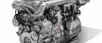
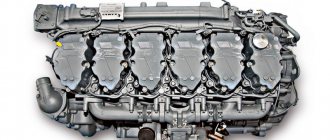
The Vladimir Motor Plant produces high-quality diesel engines used for various equipment: tractors, asphalt pavers, road machines, rollers, etc. The D 144 four-stroke engine enjoys well-deserved popularity among domestic and foreign automakers due to a large number of advantages: it is economical, reliable, relatively cheap. To restore the performance of this power unit, the car market has a large number of necessary spare parts.
Engine device D 144
Based on this model, three main modifications are produced. The difference between these internal combustion engines is the number of nominal crankshaft revolutions: 1500; 1800; 2000 rpm. According to these values, each motor develops a certain maximum power in the range from 37 to 60 horsepower.
Each of the modifications, depending on the design features, operating conditions, is equipped with the following mechanisms and devices:
- Compressor.
- Automatic stop system.
- Gear type hydraulic pump.
- Electrical network 12V, 24V.
When marking each model, an additional index is added to the basic designation, indicating the features of the configuration.
Basic technical characteristics D 144
| Cylinder diameter | 105/120 mm |
| Cylinder volume | 4.15 l. |
| Engine weight d 144 | 375 - 390 kg |
| Length | 919 mm |
| Height | 848 mm |
| Width | 741 mm |
The main components and systems that are part of all models of the D 144 engine:
- Motor crankcase.
- Connecting rods.
- Cylinders.
- Pistons.
- Crankshaft.
- Electrical equipment, including hinged.
- Supply system.
- Gas distribution.
- Cooling.
- Lubricants.
General information about the engine
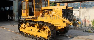
Diesel power unit D-144 produced by VMTZ is installed on more than 10 different models of equipment. These machines include T-40, LTZ-55 and T-28 tractors, concrete mixers, rollers, asphalt pavers and loaders. It is also widely used in diesel welding units and as a drive for small power plants. The obvious advantages of this motor include the availability of spare parts, good maintainability, high service life and ease of operation.
D-144 engine
Main characteristics
Motor D-144 has the following overall dimensions:
- the length of the power unit is 919 mm;
- the width, in turn, is 741 mm;
- the height is 848 mm.
There are three modifications of the D-144 engine. The first version of this motor has a power of 60 hp. and the following characteristics:
- crankshaft rotation speed is 2000 rpm;
- maximum torque is 221 newtons per meter;
- fuel consumption is 242 grams per watt per hour.
The 50 horsepower version of the motor has the following features:
- the speed is 1800 rpm;
- torque has a value of 205 newtons per meter;
- the fuel consumption indicator stopped at around 241 grams per watt per hour.
The third version of the motor has a capacity of 37 horsepower. This unit has the following specifications:
- the number of revolutions of the crankshaft per minute - 1500 rpm;
- torque - 192 N × m;
Be sure to read: Alteration of the steering wheel on MTZ
Each of these versions of the D-144 ICE is equipped with four cylinders arranged in a row. The cylinder diameter is 120 mm, in a modification with a power of 37 hp. - 105 mm. Below are the features common to each of the three versions of the diesel:
- the working volume of each of the cylinders is 4.16 liters;
- the weight of the D-144 engine in running order varies from 375 to 390 kg, depending on the configuration;
- the value of oil consumption ranges from 0.3 to 0.5% of the original amount. This value depends on the amount of fuel used.
Description of the crankcase and elements of the cylinder-piston group of the engine D 144
The crankcase of a diesel engine is a body part. It serves as the basis for the placement of working units, components and parts of an internal combustion engine. The design of the base part provides special supports for installing the crankshaft. The upper part of the crankcase is bored out for the installation of cylinders.
Cylinders are made of high-strength cast iron. The outer surface of each cylinder is decorated with special ribs to improve cooling. With the help of special mechanical processing of the inner surface of the cylinders, mirror smoothness is given. If during operation the cylinders are damaged, worn out, they are not subject to boring and other types of restoration. Such elements are replaced with new samples.
Mounted and electrical equipment D 144
This system consists of glow plugs, starter and alternator. As mentioned above, the voltage in the system can be either 24 or 12 volts. It all depends on the model of the diesel engine. The power parameters of the working nodes are shown in the table:
| at 12V | at 24V | |
| Generator power | 700 W | 1000 W |
| Starter power | 6 l. With. | 8 l. With. |
Attachment:
- Belt drives of the generator, cooling system fan, compressor drive.
- Elements of the engine lubrication system D 144 - filler neck, control oil dipstick, filter, oil pan.
- Gas distribution system drive.
- Fuel filters, injection pump, injectors.
- Collectors (exhaust, intake).
- Coolant deflector.
- Fan.
- Starter.
- Generator.
- Flywheel housing.
Engine device
The principle of operation of the D-144 engine does not differ from other internal combustion engines. The power unit is started by means of a starter, and in some models of equipment this device is automatic. The starter voltage can be either 12 or 24 V, while its power varies in various modifications and can be 4 or 5.9 kW. The unit is equipped with spark plugs.
The basis of the motor design is a one-piece body on which the cylinder heads are mounted. At the same time, the cylinder block as such, as well as on other air-cooled internal combustion engines, is not provided in the D-144. There is also a piston group consisting of pistons with a diameter of 105 mm. There is also a combustion chamber.
Fuel pump diagram
Fuel supply is carried out using an in-line injection pump - a high-pressure fuel pump. D-144 is an injection engine with closed nozzles. Also in the design of this motor there are two fuel purification systems. Both of these fuel filters - coarse and fine - are versatile and easily replaceable. In addition to the fuel filter, the D-144 has an inertial oil air filter.
The engine lubrication system consists of an oil pump, a filter and a radiator for cooling the lubricant. The lubrication process in the D-144 occurs by spraying a pressurized liquid onto all surfaces of the motor. The oil filter is easily replaceable, and the cooling radiator is a metal tube.
Early versions of the D-144 had a passive cooling system. However, the latest versions of the motor include a forced cooling system. Its main element is an automatic axial fan with a belt drive that transmits torque.
The design of the engine provides an electric generator that provides alternating current. The generator has a rectifier that converts alternating current to direct current, and a voltage regulator. The voltage of this device is 12 or 24 V, and its power varies from 700 to 1000 watts.
Be sure to read: MTZ disassembly
Features of the gas distribution system of the engine D 144
In diesel engines of the Vladimir plant, each cylinder has its own head. The head material is aluminum alloy. Thanks to the external cooling fins, as well as the air gap between adjacent body parts, reliable heat removal from the combustion chambers is ensured. The heads are equipped with inlet-outlet valves. Nozzles and decompression devices are installed in prepared threaded holes. The decompressor is necessary to ensure a quick start of the diesel engine at low ambient temperatures.
Engine lubrication system D 144
The lubrication system of the D 144 engine family is of a mixed type. Here, engine oil is supplied to the rubbing surfaces of working units and parts forcibly under pressure and by spraying. In addition to its lubricating function, oil performs efficient heat dissipation. To create the necessary pressure in the system, a pump with a gear block is used. A special valve (reducing valve) is built into the system, which is designed to control the pressure of the lubricating fluid.
The reliability of the internal combustion engine and the vehicle as a whole depends on the quality of the functioning of the lubrication system. To ensure stability in the operation of a diesel engine, the following measures must be taken:
- regularly check the engine oil level;
- make up for the missing amount.
During engine maintenance, the lubricant and oil filters are replaced. The oil cooler is also regularly maintained. The range of maintenance works for the D 144 engine includes items for adjusting valve clearances and the fuel supply advance angle.
2. Applicability of D-144, its main characteristics
The versatility of this motor deserves special attention. D-144 at various times was installed in the following equipment:
- tractors: T-28, LTZ-55, T-40;
- track vehicles: PRM, MSSU;
- units for the implementation of welding work - ADD;
- power plants of various types - ED-16-T400, AD-16-T400;
- compressor stations - PKSD;
- much more.
Such prevalence is easily explained by the large number of advantages of using this engine. Ease of use is one of the most important. To perform maintenance and even to replace any parts, a minimum number of tools and skills are required. With all this, the resource of this engine is quite large.
All characteristics can be divided into main groups - basic, which take place in all varieties without exception, and unique, differing.
2.1 Basic characteristics
The main parameters of the D-244 are as follows:
- cylinder size (its diameter) - 105/120 mm;
- working volume of the cylinder - 4.16 l;
- torque reserve value - 15% (nominal);
- oil consumption in the form of waste - 0.3-0.5%, depending on the amount of fuel consumed;
- diesel engine weight, depending on the condition (together with filling tanks / dry) - 375-390 kg.
The parameters indicated above are universal, identical regardless of the specific modification. At the same time, there are a large number of different nuances. One of the main features is the overall dimensions. They are also the same on all types of the D-144 motor:
- length - 919 mm;
- width - 741 mm;
- height - 848 mm.
Also, it is the overall dimensions that determine the possibility of installing the motor in equipment of various types. An important factor is the power of the motor. It allows you to implement a variety of tasks. The engine has proven itself well in various operating conditions - both at extremely low temperatures and vice versa - at high ones.
2.2 The main characteristics of various types of the D-144 engine
All D-144 engines are divided into 3 types according to the output power. So, models with an operating power of 44.1 kW (60 hp), have the following performance characteristics:
- crankshaft rotation speed - 2,000 rpm;
- cylinder volume (working) - 4.16 l;
- number of working cylinders - 4 pcs.;
- torque, maximum - 221 N × m;
- the value of the specific fuel consumption gram / W × h - 242.
There are also 50 and 37 hp models. 50 hp engine have the following operating parameters:
- crankshaft rotation speed - 1,800 rpm;
- working volume of cylinders - 4.16 l .;
- maximum torque, N × m - 205;
- specific fuel consumption, grams / Wh - 241;
- number of working cylinders - 4.
37 hp engine:
- number of working cylinders - 4;
- the working volume of each, l - 4.16;
- the value of the maximum torque, rpm - 1,500;
- cylinder diameter, mm - 105;
- maximum torque, N × m - 192.
Currently, VMTZ is developing a modified version of this type of engine. The reason for this is its demand in various spheres of human activity. Air cooling is important. It is due to this, in part, that a relatively low fuel consumption is achieved with a sufficiently high output power.
Cooling system D 144
In order for the technical characteristics of the D 144 engine to be maintained for a long time, it is necessary to provide reliable high-quality cooling, regardless of the season and other external operating conditions. The lion's share of work on heat removal is performed by an axial fan.
Directed air flows pass through the gaps and ribs of hot parts and assemblies of the internal combustion engine. With the help of a special casing and deflectors installed between the working cylinders, the air moves freely in a given direction. To control the intensity of air flows in the air intake, a special rotary disk is installed.
Timing and cooling system of diesel D-144
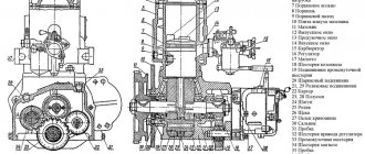
The timing mechanism of the D-144 engine of the T-40 tractor (Fig. 3) provides a 4-stroke cycle in the diesel cylinders and consists of gas distribution gears, a camshaft, a valve mechanism with a drive, including pushers, rods, racks of rocker arms and rocker arms , valves, valve springs and valve mounting parts.
Timing works as follows. Gear 28 of the crankshaft through the intermediate gear 25 and gear 24 drives the camshaft 2.
The camshaft 2, when rotating with its cams, raises the pushers 3 and through the rods 15 and rocker arms 14 opens the intake and exhaust valves 21. With further rotation of the camshaft, the cam protrusion moves away from the pusher and under the influence of the springs the valve closes.
The rocker, rod and pusher return to their original position. Then this cycle is repeated again in accordance with the selected valve timing.
Rice. 3. Timing engine D-144 tractor T-40
1 - crankcase; 2 - camshaft; 3 - valve lifter; 4, 9 - sealing rings; 5 - decompressor roller; 6 - lever; 7 - rail; 8 - pusher guide bushing; 10, 18, 20 - springs; 11— strap: 12—valve cover; 13 - adjusting screw; 14 - valve rocker; 15 - pusher rod; 16 - rod casing; 17 - valve plate; 19 - valve cracker; 21 - valves; 22 - valve seat; 23 - piston; 24 - camshaft gear; 25 - intermediate distribution gear; 26 - hydraulic pump drive gear; 27 - fuel pump drive gear; 28 - crankshaft gear; 29 - drive gear of the oil pump; 30 - driven gear oil pump
In order for the gas distribution mechanism of the D144 diesel engine of the T40 tractor to work synchronously with the fuel supply system, the camshaft gears - the intermediate and fuel pump gears - must be installed respectively according to the marks on the gears.
Before adjusting the clearances in the valves, the wedge of the rear cardan is removed and, by moving the shaft along with the steering wheel towards itself, the cardan shaft is released and taken to the side. While holding the screw 13 with a screwdriver from turning, release the lock nut of the adjusting screw.
While supporting the screw locknut with a wrench, turn the screw in and out until a gap of 0.3 mm is obtained, using a feeler gauge. Without removing the probe, tighten the locknut of the adjusting screw, turn the rod by hand and make sure that the gap remains unchanged and that the rod is not bent.
Turn on the decompressor. By turning the crankshaft clockwise by a special bolt, set the piston of the first cylinder to the position of the end of the compression stroke. Turn off the decompressor.
Measure the gap in the first cylinder between the rocker heads and the ends of the inlet and outlet valve stems. Adjust gaps if necessary.
Then, to adjust the valves of each next cylinder, turn the crankshaft 1/2 turn clockwise and carry out the adjustment in the sequence corresponding to the order of operation of the cylinders (1-3-4-2).
During normal operation of the D-144 diesel engine of the T40 tractor, the valves remain tight for a long time.
To prevent crackers from falling out and valves breaking along the undercut, do not break pairs of crackers when disassembling the valve mechanism and install them on other valves. The rocker rack nuts are tightened with a force of 60-80 N (6-8 kgf) on a shoulder of 0.5 m.
Decompression mechanism diesel D144
The decompression mechanism of the D-144 diesel engine of the T40 tractor (see Fig. 3) serves to facilitate the start of an unheated diesel engine and for an emergency stop of the diesel engine.
The mechanism consists of a rail 7 and four levers 6 pivotally connected to the rail. The levers are rigidly connected to the rollers 5, which enter with their milled ends into the grooves of the intake valve pushers.
When the rack 7 moves, levers 6 with rollers 5 turn, which raise the pushers, and they, in turn, open the intake valves through the rods 15 and rocker arms. In the off position (levers turned forward), the milled end of the rollers does not lift the pushers.
Engine cooling system D-144
The cooling system (Fig. 17) consists of a fan, a guide casing, deflectors, a fan belt drive and serves to remove heat from cylinders and heads. The surfaces of the cylinders and heads are finned, which significantly increases the cooling surface and improves heat dissipation.
Rice. 17. D144 diesel engine cooling system
1 - fan casing; 2 - rear deflector; 3 - stud fastening the middle deflector; 4 - middle deflector; 5 - front deflector
The fan of the D-144 engine cooling system of the T-40 tractor (Fig. 18) creates an air flow that serves for intensive heat exchange of cylinders and heads. It is installed on the right side of the diesel engine, attached with a clamp to the top of the timing gear cover.
When the diesel engine is running, the fan rotor blows air under the fan casing, into the space between the ribs of the cylinders and heads. The fan casing, rear, middle and front deflectors (guide plates) are used to direct the air flow.
The fan is driven by a V-belt drive from a two-stranded pulley mounted on the crankshaft.
Operating conditions of the engine cooling system D-144
An indicator of the normal operation of the cooling system is the temperature of the oil in the diesel line, which should be in the range of 40-120 ° C.
When the oil temperature in the line rises above 120 ° C, the diesel engine is stopped and faults are eliminated, the causes of which may be:
- weak tension, wear or breakage of the fan drive belts (if the fan drive belts break, a red lamp lights up on the instrument panel) - tension or replace the belts; - clogging of the intercostal space of the cylinders and cylinder heads - they are cleaned by removing the fan casing, the middle and rear deflectors (when installing the middle deflectors on a diesel engine, they are placed with the wide part down); - clogging of the protective mesh of the fan - remove the mesh and clean it from dust, dirt, etc.; - loosening the fan pulley nut - tighten the nut.
Rice. 18. Fan of the engine cooling system D-144
1- impeller (rotor); 2 - thrust sleeve; 3 - coupling bolt; 4 - fan shaft; 5 - pulley; 6 - nut; 7 - guide apparatus
Regulation of the thermal regime of diesel engine D-144
The thermal regime of the engine is regulated by means of a disk mounted on the protective grid of the fan (at the inlet of cooling air to the fan) (see Fig. 18), as well as by turning the oil cooler on and off with a switch located on the centrifuge housing.
In the cold season (at a temperature of +5°C and below), the oil cooler is disconnected from the oil system, and the disk is installed on the protective grid of the fan (for a diesel engine with seasonal regulation of the thermal state at an ambient temperature of below 40 °C is ensured by installing a disk on the fan and loading at least 40% of its rated power).
When the ambient temperature is above +5°C, the radiator is included in the system, and the disk is removed from the fan and deposited.
During operation, it is necessary to ensure that the fan casing does not have dents, and the deflector parts are not bent. These shortcomings must be corrected. Do not allow the grooves (streams) of the pulleys to be contaminated with oil, fuel and dirt.
If one of the fan drive belts fails, the belts are removed and two new belts of the same length are installed. Used belts are selected in separate sets and only after that they are installed on a diesel engine. They must be the same length.
Completing new belts with used belts is not allowed.
Tractors T-40 are shipped from the factory with a radiator included in the lubrication system. The throttling disk is not installed on the fan, it is placed in a tool box.
The bearings installed in the fan do not require lubrication during operation until they are rejected.
Fig.19. Fan drive and engine generator D-144
1 - generator bracket; 2 - bolt; 3 - generator; 4 - tension bar; 5 - fan pulley; 6 - hairpin; 7 - washer; 8 - nut; 9 - pulley; 10 - crankshaft pulley
The tension of the fan and generator drive belts is regulated by changing the position of the generator (turning it). Before adjustment, loosen the nut 8 (Fig. 19) fastening the tension bar and the nuts of the bolts 2 fastening the generator, and after adjusting, tighten them.
Each belt must be tensioned so that when you press it with a force of 40 N (4 kgf), the belt deflection arrow is 15-22 mm (check using two-dimensional metal rulers and a spring dynamometer).
The belt tension is checked in the middle part of the branch between the crankshaft and fan pulleys. Particular attention is paid to the correct tension of the belts in the first 60 hours of diesel operation.
