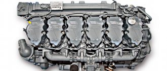
KAMAZ valve adjustment with Cummins engine
Cummins engines, which are now installed on KAMAZ vehicles, are very reliable and have a long service life. They require mandatory regular maintenance. Among other things, periodic adjustment of KAMAZ valves is extremely important. The official instructions of the automaker indicate that the adjustment of KAMAZ valves with a Cummins engine should be carried out after at least 240,000 km of run. But, in addition to performing planned work, the need for it may also appear due to other reasons.
The first signs indicating that it is necessary to adjust the valves of the KAMAZ internal combustion engine are a knock that occurs under the hood, an increase in the “appetites” of the power plant or a decrease in its power. Ignoring these signs and the lack of timely adjustment of the valves leads to the fact that the subsequent use of the engine may lead to new malfunctions in the internal combustion engine. Therefore, it is worth knowing the procedure for adjusting KAMAZ valves with your own hands.
Why does valve imbalance occur?
It must be realized that do-it-yourself adjustment of KAMAZ valves is useless if the initial cause of the malfunction is not eliminated. Possible causes are breakdowns that are associated with improper or untimely maintenance:
- incorrect setting of valve clearances or incorrect sequence of tightening the bolts on the cylinder head during the preliminary maintenance of the motor;
- physical wear or malfunction of timing parts;
- the use of low-quality cooling fluid, which led to overheating of the motor;
- a faulty air filter that lets not only air into the cylinders, but also dirt;
- the use of contaminated or low-quality engine oil, untimely replacement of the filter or the oil itself;
- fuel that does not burn to the end due to other breakdowns or poor quality of the fuel itself.
The procedure for adjusting KAMAZ valves with a Cummins engine: gaps
The procedure for adjusting KAMAZ valves and the procedure for adjusting KAMAZ valves with a 6-cylinder Cummins engine do not differ from each other.
Adjustment of KAMAZ Euro-4 valves implies the preliminary removal of the rocker cover from the motor. To do this, you must disconnect the crankcase breather from this cover. First, the oil drain lines are removed from the breather.
Then it is necessary to disconnect the fitting related to the breather tube from the rear side of the cover of these rocker arms, then it is removed from the rear camshaft housing. For this purpose, it is necessary to loosen the clamp related to the breather tube, then pull the fitting in a vertical direction. Then, to provide access to the valves, you need to remove the rocker cover with gasket.
KAMAZ Euro-1 valves are adjusted when the temperature of the cooling liquid does not exceed 60 degrees. Any KAMAZ valve adjustment scheme implies this.
After turning the crankshaft, you need to set the dead top point of the piston of the 1st cylinder of the engine.
On an engine that does not have a system that recirculates used gases, the dead top point is set as follows: they put a sensor ring that shows the engine speed so that its part devoid of grooves is at 12 o'clock.
In the case when both rocker arms on the first cylinder are not released for regulation, it is necessary to rotate the crankshaft by making a full turn.
KAMAZ Euro-3 valve adjustment scheme
On a motor on which a used gas recirculation system is installed, the location of the dead top point of the 1st cylinder is a torsional vibration damper or a sensor ring that indicates the engine speed.
It is necessary to install the ring or damper so that the mark is at 12 o'clock.
If it was not possible to release the rocker arms of the 1st cylinder, you still need to turn the crankshaft 360 degrees. Then you can start measuring the valve and rocker clearances.
This is exactly the sequence for adjusting KAMAZ valves.
KAMAZ valve clearances with Cummins engines
In this position of the crankshaft, the gaps of such rocker arms are measured:
- E - exhaust valve, I - inlet;
- for engines with 14 cylinders: 1E, 1I, 2I, 3E;
- for engines with 16 cylinders: 1E, 1I, 2I, 3E, 4I, 5E.
The maximum intake valve clearance is 0.381 mm, the minimum is 0.152 mm, for the exhaust valve the minimum clearance is 0.381 mm, the maximum is 0.762 mm.
The clearance is set correctly if the feeler gauge encounters only slight resistance when passing between the crosshead and the rocker seat.
Source: https://gruzovik.biz/articles/regulirovka-klapanov-kamaz-s-dvigatelem-cummins
Preparation for adjusting valves on the GAZelle
As before, the valves can be adjusted independently. Of course, the changes that affected GAZelle-Business affected the power unit - it changed fuel from gasoline to diesel fuel. However, the structure of the engine in its basic state remained the same.
The initial stage in adjusting the valve mechanism on the GAZelle is engine cooling. For this, the car needs to stand for several hours. At this time, it is best to prepare the necessary tools.
You may need a ratchet wrench, open-end wrench, feeler gauge, screwdriver, and engine oil for this procedure.
The need to replace the timing occurs in the following cases: belt failure (rupture or wear) and the development of a mileage resource.
The basic principles of diagnostics and repair of Cummins ISBe engines do not differ much from engines of other models. The article discusses the main types of faults that are clearly manifested during operation, as well as ways to eliminate them.
Preparation is complete, the hood is open, and now you need to get to the valve cover. For this purpose, the clamp is loosened and the breather pipes and high pressure pipes are disconnected from the nozzles.
The next step is to retract the fuel frame, for which the nuts are loosened. The nozzles must be removed by first removing the clamps from them and from the fittings. All this allows you to remove the cover and inspect the valves and their gaps, which must be adjusted.
Timing mechanism CUMMINS ISB
| Valve adjustment is performed only at the intervals specified in the Operation and Maintenance Manual (Owner's Manual), or when it is necessary to remove the rocker arms and (or) unscrew the adjusting screws during engine repair. Premature increase in valve clearance indicates incorrect adjustment after the previous repairs, worn valve stems, crossheads, pushrods or rocker arms*. Free movement of the rocker arms and the need for frequent adjustment of valve clearance can also indicate wear on the camshaft lobes or tappets. If there is no wear on the rocker arms, valve stems, crossheads and push rods, the tappets and/or camshaft lobes may be worn. |
| WARNING Batteries can emit explosive gases. To reduce the risk of injury, be sure to ventilate the area before servicing batteries. To avoid sparking, disconnect the negative (-) battery cable first and reconnect it last. |
- Disconnect batteries.
- Remove rocker cover and gasket.
| Previous Next |
| On 3.9L and 5.9L engines without EGR, install the engine speed sensor ring at the front of the engine so that the non-slotted part is at the 12 o'clock position. If both rocker arms of cylinder #1 are free, proceed to the next step. If both rocker arms of cylinder #1 are not free, rotate the crankshaft 360 degrees. | SMALL | MEDIUM | LARGE |
| Previous Next |
| On all 4.5L and 5.9L EGR and 6.7L engines, install the vibration damper/engine speed sensor ring so that the TDC mark is at the 12 o'clock position. If both rocker arms of cylinder #1 are free, proceed to the next step. If both rocker arms of cylinder #1 are not free, rotate the crankshaft 360 degrees. | SMALL | MEDIUM | LARGE |
| Previous Next |
| SMALL | MEDIUM | LARGE |
| Previous Next |
| With this crankshaft position, you can measure the clearance for the following rocker arms: (E = exhaust valve, I = intake valve) 4-cylinder engine: 1I, 1E, 2l and 3E; 6-cylinder engine: 1I, 1E, 2I, 3E, 4I and 5E. | SMALL | MEDIUM | LARGE |
| Previous Next |
| Clearance limits | |||
| mm | in | ||
| Inlet valve | 0.152 | MIN | 0.006 |
| 0.381 | MAX | 0.015 | |
| Exhaust valve | 0.381 | MIN | 0.015 |
| 0.762 | MAX | 0.030 |
| Measure the clearance by inserting a feeler gauge between the rocker arm seat and the crosshead. If the clearance is out of specification, loosen the locknut and adjust it. | inch | |
| Inlet valve | 0.254 | 0.010 |
| Exhaust valve | 0.508 | 0.020 |
Tighten locknuts and recheck valve clearances.
Torque: 24 nm [212 in-lb]
SMALL | MEDIUM | LARGEPrevious Next| Using the crankshaft turner, part number 3824591, rotate the crankshaft 360 degrees. Using the above procedures and specifications, measure the clearance for the following rocker arms: (E = exhaust valve, I = intake valve) 4-cylinder engine: 2E , 3I, 4E and 4I6-cylinder engine: 2E, 3I, 4E, 5I, 6I and 6E. Recondition if necessary. | SMALL | MEDIUM | LARGE |
| Previous Next |
| Use the crankshaft turning tool, part number 3824591, to set the No. 1 cylinder piston to TDC. | SMALL | MEDIUM | LARGE |
| Previous Next |
To determine TDC when adjusting valve clearances on marine engines, turn the crankshaft so that both rocker arms (inlet and exhaust valves) of cylinder No. 1 or No. 6 move freely.NOTE: For a more accurate TDC reading, remove the injector from cylinder #1 and use the stem and dial indicator | SMALL | MEDIUM | LARGE |
| Previous Next |
| In this position of the crankshaft, the clearance for the following rocker arms can be adjusted: (E = exhaust valve, I = intake valve) 4-cylinder engine: 1I, 1E, 2l and 3E; 6-cylinder engine: 1I, 1E, 2I, 3E, 4I and 5E. | SMALL | MEDIUM | LARGE |
| Previous Next |
| Loosen locknuts and adjust valve clearances. | inch | |
| Inlet valve | 0.254 | 0.010 |
| Exhaust valve | 0.508 | 0.020 |
Tighten locknuts and recheck valve clearances.
Torque: 24 nm [212 in-lb]
SMALL | MEDIUM | LARGEPrevious Next| Using the crankshaft turner, part number 3824591, rotate the crankshaft 360 degrees. Using the above procedures and specifications, continue to adjust the valve clearances. (E = exhaust valve, I = intake valve) 4-cylinder engine: 2E, 3I, 4E and 4I; 6-cylinder engine: 2E, 3I, 4E, 5I, 6I and 6E. | SMALL | MEDIUM | LARGE |
| Previous Next |
| WARNING Batteries can emit explosive gases. To reduce the risk of injury, be sure to ventilate the area before servicing batteries. To avoid sparking, disconnect the negative (-) battery cable first and reconnect it last. |
- Install the gasket and rocker cover.
- Connect batteries.
- Start the engine and check for leaks.
Cylinder head assembly V=6.7 (6ISBe, 6ISDe) 4936081/3977225/3977221
| Ref No | part number | Part Description | Required | Remarks |
| PP43066 | cylinder head | Cylinder Head | ||
| 1 | 3927063 | Fracture Resistant Screw | 26 | |
| 2 | 4932210 | Cylinder Head Gasket | 1 | |
| 2831474 | cylinder head | 1 | Purchase 4936081 | |
| 3802924 | Intake Valve Kit | 12 | ||
| 3 | 3940123 | Valve Collet | 2 | |
| 4 | 3955393 | Valve Stem Seal | 1 | |
| 5 | 3940735 | Intake Valve | 1 | |
| 4 | 3955393 | Valve Stem Seal | 12 | |
| 3802967 | Exhaust Valve Kit | 12 | ||
| 3 | 3940123 | Valve Collet | 2 | |
| 6 | 3940734 | Exhaust Valve | 1 | |
| 7 | 4936080 | Valve Spring | 24 | |
| 8 | 3943198 | Valve Spring Retainer | 24 | |
| 2831475 | cylinder head | 1 | ||
| 9 | 3914035 | expansion plug | 13 | |
| 10 | 3920706 | expansion plug | 11 | |
| 11 | 2831476 | cylinder head | 1 | |
| 12 | 3945093 | expansion plug | 7 | |
| 13 | 3945094 | expansion plug | 2 | |
| 14 | 4893244 | Valve Insert | 24 |
Rocker arm (cylinder assembly) (ISBe) 4995602
| Ref No | part number | Part Description | Required | Remarks |
| RL9826 | rocker | Rocker Lever | ||
| 1 | 3943626 | Valve Crosshead | 12 | |
| 2 | 3941253 | push rod | 12 | |
| 4995602 | Rocker Lever Assembly | 6 | ||
| 3 | 3990127 | Hexagon Flange Head Cap Screw | 2 | |
| 4 | 4928699 | Rocker Lever Shaft | 2 | |
| 5 | 3964908 | Rocker Lever Support | 1 | |
| 4995603 | rocker | 1 | ||
| 6 | 4994198 | Rocker Lever Socket | 1 | |
| 4995605 | rocker | 1 | ||
| 7 | 3927692 | Heavy Hexagon Nut | 1 | |
| 8 | 3959128 | Rocker Lever Adjusting Screw | 1 | |
| 9 | 4994197 | Rocker Lever Ball | 1 | |
| 10 | 3941928 | rocker | 1 | |
| 4995604 | rocker | 1 | ||
| 6 | 4994198 | Rocker Lever Socket | 1 | |
| 4995606 | rocker | 1 | ||
| 7 | 3927692 | Heavy Hexagon Nut | 1 | |
| 8 | 3959128 | Rocker Lever Adjusting Screw | 1 | |
| 9 | 4994197 | Rocker Lever Ball | 1 | |
| 11 | 3941927 | rocker | 1 |
Camshaft 3954099 / 3979506 6ISBe
| Ref No | part number | Part Description | Required | Remarks |
| PP41365 | Camshaft | camshaft | ||
| 3954100 | Camshaft | 1 | Buy Lower Level Components. | |
| 1 | 3954111 | Ring Dowel | 1 | |
| 2 | 3955069 | Speed Indicator Ring | 1 | |
| 3979506 | Camshaft | 1 | ||
| 3 | 3904483 | Pin Dowel | 1 | |
| 4 | 3954099 | Camshaft | 1 | |
| 5 | 4895877 | Socket Head Cap Screw | 2 | M6 X 1 X 25. |
| 6 | 5258931 | Camshaft Thrust Support | 1 | |
| 7 | 3925883 | Hexagon Flange Head Cap Screw | 2 | M8 X 1.25 X 16. |
| 8 | 3955152 | Camshaft gear | 1 |
Source: https://cummins-zapchasti-isf-isb-isl.nethouse.ru/posts/2742630
Why adjust valves?
The operation of the engine inevitably causes a growing imbalance of working units and parts. This happens both as a result of regular operation and in case of violations of the rules for the operation of diesel units. The result is deviations in valve clearances from the optimum.
Prolonged operation of the engine, which has signs of malfunction, accelerates its wear and potentially threatens with more serious breakdowns, up to the complete failure of the unit. Before adjusting the valve clearances, the causes that caused the imbalance should be eliminated. Otherwise, the problem will reappear soon. The main reasons are:
- previously incorrectly adjusted clearances and errors when tightening bolts in
- cylinder head;
- physical wear or other breakdowns in the timing units;
- the use of low-quality coolant, which caused the engine to overheat;
- air path pollution;
- engine oil contamination;
- breakdowns associated with incomplete combustion of fuel;
- excessively long work at high speeds;
- abuse of starting the engine with the help of ether.
Clear signs that the engine requires immediate maintenance are a metallic knock in the running unit, an increase in fuel consumption and a drop in unit power.
Even if there were none of the above incidents, every 150-200 thousand kilometers it is necessary to adjust the valves simply for preventive purposes.


