Technical characteristics of the tractor T-170, bulldozer T-170
Tractor T-170, bulldozer T-170
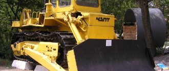
(based on the T-10.01 tractor) - was developed and put into mass production at the Chelyabinsk Tractor Plant) in Chelyabinsk. The T-170 tractor, the T-170 bulldozer is a Soviet agricultural and industrial caterpillar tractor, which is a more modernized version of the T-100 tractor. Tractor T-170, bulldozer T-170 is available in two versions: conventional and swamp (T-170B) with an increased track area.
Bulldozer T-170, tractor T-170 ChTZ
Tractor T-170, bulldozer T-170 is used as part of a bulldozer-ripping unit, including as a base machine for TR-12 and TR-20 pipelayers, pile driver.
Tractors and bulldozers T-170 are representatives of the most massive traction classes of 10-15 tons. These bulldozers work in various industries, as well as in road and municipal services, and in logging.
Bulldozer T-170, tractor T-170 in the timber industry.
Tractors and bulldozers T-170 ChTZ have a long service life and increased maintainability, which makes it possible to operate bulldozers and tractors T-170 in difficult climatic conditions.
Engine
Bulldozer T-170, tractor T-170 is supplied with a four-stroke diesel engine D-160/D-180, turbocharged, up to 180 hp.
Engine D-160 ChTZ
D-160 and D-180 engines have the following specifications:
Specifications D-160 / D-180 | |
| Engine brand | D180.111-1(D-160.11) |
| engine's type | Four-stroke diesel, turbocharged, multi-fuel |
| Engine power, kW (hp) | 125 (170) |
| Specific fuel consumption, g/kW*h (g/l.s.h.) | 218 (160) |
Hydraulic system of the bulldozer T-170, 130
______________________________________________________________________________________________
The separate-aggregate hydraulic system of the T-170/130 bulldozer is used to control mounted, semi-mounted and trailed implements operating in combination with a tractor. Mounted systems are used to attach mounted and semi-mounted implements to the tractor. For the tractor (bulldozer) T-170, two types of mounted systems are provided, front and rear. Universal separate-aggregate hydraulic and hinged systems consist of a drive with a hydraulic pump, a P160 hydraulic distributor, two hydraulic tanks interconnected by turbo lines. The hydraulic pump through the high pressure hydraulic line supplies the working fluid from the hydraulic tanks to the hydraulic distributor and from it to the hydraulic cylinders. The pump drive is mounted in the casing of the diesel distribution gears. The drive gear is in constant mesh with the large intermediate gear of the diesel engine. Shaft and gear bearings are splash lubricated from the diesel lubrication system. The NSh-100A-ZL gear pump is used to periodically pump the working fluid into the cylinders of the mounted system. The pump is driven by the drive shaft. The drive shaft is connected to the pump shaft by means of a splined coupling, which serves to compensate for the radial beats of the connected shafts. Filling oil into the pump drive for lubrication of splined couplings is carried out through the breather plug to the level of the control plug. The R-160 hydraulic distributor of the T-130/170 bulldozer is designed to control the flow of working fluid in the hydraulic system and distribute it between different groups of hydraulic cylinders. The hydraulic distributor consists of distribution, bypass and safety devices. The distributing device consists of three spools, each of which, independently of the others, determines the four working positions of the corresponding group of hydraulic cylinders, for example: for hydraulic cylinders of the rear linkage mechanism - LOWER. NEUTRAL. CLIMB. FLOATING. Moreover, the positions NEUTRAL and FLOATING are fixed. At the end of the necessary stroke of the pistons of the T-170 hydraulic cylinders for LIFT and LOWER, the control lever should be released and the spool will return to the NEUTRAL position under the action of the spring. The differential type bypass device consists of a valve with a guide, a spring and a system of holes, which, when the spools are in the NEUTRAL or FLOATING positions, provide unloading of the hydraulic pump. The safety device, consisting of a ball safety valve with a spring and an adjusting screw, limits the maximum pressure in the T-170/130 hydraulic system and works in conjunction with a bypass device, ensuring that the working fluid is bypassed from the high pressure cavity to the drain when the safety valve adjustment pressure is reached. The check valve prevents the passage of the working fluid from the hydraulic cylinders through the bypass device to the drain during the switching of the spools. The R-160 hydraulic distributor is installed on the right under the cabin floor. The hydraulic tanks are connected by a power pipe, in which a filter with a bypass valve is installed. The cavities of the hydraulic tanks are connected by pipelines in the upper and lower parts and with the atmosphere through the breather valve in the right hydraulic tank. The working fluid is filled through the filler filter in the right hydraulic tank, the level is controlled by the viewing restrictive window in the right hydraulic tank. The working fluid is drained from the hydraulic tanks through the drain hole in the pipeline connecting the hydraulic tanks at the bottom. The hydraulic system filter T-130/170 sectional consists of three removable paper filter elements installed in the power pipe. For symmetrical installation of the filter, a sleeve is installed in the pipe. The drained working fluid from the P-160 hydraulic distributor enters the power pipe and overflows through the filter into the left (along the way) hydraulic tank. When the filter is clogged and the pressure rises above 0.2 MPa (2 kgf / cm2), the control lamp of the filter clogging indicator on the instrument panel goes out, the filter bypass valve is activated and the working fluid is poured into the left tank, bypassing the filter. In the absence of a clogging indicator or a malfunction, replace the filter elements after 2000 hours. On the suction line of pumps (NSh-100A-ZL, NSh-32-L) there are pipelines (siphons) with plugs. When the plugs are removed, the oil flow to the pumps is interrupted, which makes it possible to dismantle the units of the hydraulic system without draining the oil. At the end of the repair work, the plugs should be wrapped. The rear mounted system of the T-170 bulldozer is designed to attach mounted and semi-mounted machines and implements to the tractor from behind. The front mounted system is designed to attach mounted machines (implements) to the tractor from the front, a bulldozer, a puller, and others. The lifting and lowering of attachments is carried out by two hydraulic cylinders. Double-acting hydraulic cylinders are fixed on the trunnions of the hydraulic tanks. End valves are installed in the rods of the front hydraulic cylinders T-170/130, which unload the system at the end of the piston stroke. High-pressure pipelines and hoses are connected to the hydraulic distributor with fittings and slats. Sealing is achieved by installing rubber rings and cone-sphere connection. The pipelines going forward from the hydraulic distributor serve to connect the hydraulic line to the front mounted system, and those going back to the rear mounted system and the hydraulic lines of trailed implements. Attaching implements to the left section of the P-160 hydraulic distributor simultaneously forward and backward is not allowed. On tractors of the T-170M1.03-51 type, a pipeline coming from the middle section of the distributor is additionally used to connect the hydraulic skew of the blade. The pipelines going back from the right section of the hydraulic distributor serve to connect the rear attachment system, from the left and middle sections - to connect hydraulic machines and implements with the bulldozer equipment removed. Attaching implements to the left and middle sections of the P160 distributor simultaneously forward and backward is not allowed. Working chambers of hydraulic cylinders can be connected to each pair of pipelines, ensuring the operation of the implements in accordance with the plate installed in the cab. Checking and adjusting the pressure of the working fluid in the T-170/130 hydraulic system The maximum pressure in the T-170 hydraulic system should be adjusted at a working fluid temperature of 40-60 °C. Before checking the pressure, stop the diesel engine and move the levers of the P160 distributor to the FLOATING position to connect the high pressure hydraulic lines to the drain. Failure to follow these instructions may result in an accident. To check the pressure: disconnect one of the hydraulic lines from the middle or right (along the tractor) section of the hydraulic distributor to the hydraulic cylinders of the mounted equipment; - connect the pressure gauge assembly with gasket 700-40-260-01 and adapter 261381 to the high pressure hose in the section from the hydraulic distributor (the gasket and adapter are in the spare parts kit); - plug the disconnected hydraulic line with nut 700-41-3565 and plug 700-41-3571. If the specified sections of the hydraulic distributor are inoperative, connect the pressure gauge to the high-pressure hose installed on the tractor specifically for this purpose. Start the diesel engine, set the maximum speed and move the lever of the corresponding section of the hydraulic distributor to the LIFT or LOWER position, holding it in this position. The maximum pressure in the hydraulic system should be 20 MPa. If necessary, adjust it with the valve of the hydraulic distributor safety device, for which purpose remove the protective cap, unlock the adjusting screw and, screwing or unscrewing it, change the pressure in the hydraulic system. Check the pressure every quarter turn of the adjusting screw.
______________________________________________________________________________________
___________________________________________________________________________________________
Other special equipment
MTZ-80
- Creeper MTZ-80, 82
- The design of the chassis of the MTZ-80 tractor
- Gearbox MTZ-80
- Clutch MTZ-80, 82
- Maintenance and adjustment of the MTZ-80.82 checkpoint
- Starting engine PD-10
- Transfer box MTZ-80
- Adjustment of driving axles MTZ-80, 82
- Steering gear and power steering MTZ-80, 82
- The device of the brake system MTZ-80, 82
- PTO MTZ-80, 82
______________________________________________________________________________________
YaMZ-236
- Components of the cylinder block YaMZ-236 NE2, BE2
- Clutch YaMZ-181,182,183
- Clutch discs YaMZ-236, 238
- Crankshaft and piston group YaMZ-236
- Gearbox YaMZ-236
- Diagnostics and adjustment of the YaMZ-236 engine
- Fuel supply and lubrication of the YaMZ-236 diesel engine
- Clutch YaMZ-236
- HPFP and injectors YaMZ-236
YaMZ-238
- Cylinder block and piston group YaMZ-238
- Crankshaft and timing diesel YaMZ-238
- Checkpoint YaMZ-238
- Cooling and lubrication of YaMZ-238 diesel
- Clutch YaMZ-238
- High pressure fuel pump YaMZ-238
T-130
- Onboard clutches T-130
- Onboard gearbox T-130
- Diesel D-160 tractor T-130
- Undercarriage T-130
- T-130 tractor turning mechanism
- Assembly and installation of T-130 carts
- Servomechanism of onboard clutches T-130
- Clutch tractor T-130
- Clutch and mountain brake control mechanism Т-130
T-170
- Engine D-180 bulldozer T-170
- Hydraulic system of bulldozer T-170
- Bulldozer hydraulic cylinder T-170, 130
- Repair of the main gear of the bulldozer T-170, 130
- Caterpillars and rollers T-170, 130
- Carrying and running system T-170
- Assembly of T-170, 130 checkpoint units
- Tension mechanism and track roller T-170, 130
- Bulldozer equipment T-170 with a rotary blade
- Clutch adjustment T-170
- T-170 Bulldozer Transmission Details
KRAZ
- Gearbox KRAZ-255, 260
- Steering Kraz-250, 255
- Drive axle and cardan shafts Kraz-255, 260
- Clutch Kraz-250, 260
- Kraz car power steering
- Kraz car suspension
- Transfer case Kraz
- Kraz power take-off
- Kraz-6510, 65055 car brake system
- Cardan drive and drive axles Kraz-6510, 65055
- Front suspension of Kraz-6510, 65055 cars
- Steering KRAZ-6510, 65055
- Clutch Kraz-6510, 65055
Attachment T-170
Tractor T-170, bulldozer T-170 can be equipped with various attachments: straight or hemispherical blade (shovel), single or multi-tooth ripper (rooter).
Bulldozer T-170 with direct blade.
Characteristics of bulldozer equipment T-170 | ||
| blade type | Hemispherical | Straight |
| Changing the cutting angle and blade skewing angle | Screw and hydraulic braces | |
| Drawing prism volume, m3 | 4,75 | 4,28 |
| Blade width, m | 3,31 | 3,42 |
| Height at a cutting angle of 55 degrees | 1,31 | 1,31 |
| Maximum lift, m | 1,02 | 1,02 |
| Maximum depth, m | 0,44 | 0,44 |
| Maximum skew, m | 0.63 (10 deg.) | 0.63 (10 deg.) |
| Cutting angle adjustment, deg | 10 | 10 |
| Weight, kg | 2313 | 2240 |
Single-tooth ripper of the bulldozer T-170
Characteristics of ripping equipment T-170 | ||
| Type | multi-pronged | single tooth |
| Max number of teeth | 3 | 1 |
| Number of tooth positions (vertical) | 3 | 3 |
| Maximum depth, mm | 650 | |
| Loosening angle, degrees: | ||
| - with a short tip | 45 | 45 |
| - with a long tip | 30 | 30 |
| Weight, kg | 2245 | 1555 |
Tractors and bulldozers T-170 deserve a mixed rating. Their advantages include a simple design and low cost (compared to tractors of a similar class).
CHTZ DEVICE T 170
Bulldozer ChTZ T 170 has a frame structure with the following main elements:
- chassis;
- transmission;
- hydraulic system;
- engine;
- cabin.
The caterpillar-type undercarriage is based on 5-roller bogies (classic version for machines of 10 traction class), the propulsion of which is mounted on 3 points. A semi-rigid suspension with a balancing rigid beam provides the necessary structural rigidity. Optionally, 7-roller carts are installed (the best option for working on soft soils and on sloping terrain). This variation typically uses long spars and wider shoes (900 mm) to reduce ground pressure.
Running gear characteristics:
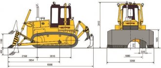
- track width - 1880 mm;
- the number of road wheels (on one side) - 5 (7);
- number of support rollers (on one side) - 2;
- the number of shoes (on one side) - 38 (45);
- type of shoes - single-ridged;
- shoe size - 500 (900) mm;
- lug height - 65 mm;
- surface pressure (for the basic version) - 0.076 MPa.
The transmission is responsible for transferring power from the engine to the drive axle. ChTZ T 170 uses a hydroserved mechanical multi-stage gearbox, supplemented by a clutch. The transmission is located at the rear of the machine. The basic gearbox includes 8 speeds forward and 4 speeds reverse. On some versions, a 6-speed gearbox is installed with the ability to block first gear. To select the speed, the lever for selecting ranges and shifting gears is used. Starting the engine is blocked when the range lever is not in the neutral position.
The braking system is based on multi-disc side clutches and band brakes.
Hydraulic system ChTZ T 170 - separate-aggregate, supplemented by a gear pump NSh-100. As part of the system, there are various nodes that change during the installation of various devices. A filter that does not affect the flow pressure is responsible for cleaning the hydraulic system. The pressure in the system is 16 MPa, the pressure of the safety valve is 20 MPa.
At the rear of the ChTZ T 170 is a frame metal cabin. A convenient viewing angle allows the driver to perform complex operations efficiently. Special supports on which the cab is mounted minimize the level of vibration transmitted to the passenger compartment. A comfortable chair with adjustments for weight and height is installed inside. The instrument panel is made in accordance with safety standards and is as informative as possible. The cabin is equipped with a heater and ventilation, air conditioning is available on request. Additional operator protection is provided by ROPS and FOPS systems.
The main characteristics of the bulldozer
Considering the technical characteristics of the bulldozer T 170, the following features of the vehicle can be distinguished:
- the ability to choose one of two types of engine 180 horsepower or 160 hp;
- a four-shaft gearbox equipped with constant mesh gears and providing the vehicle with 4 reverse and 8 forward gears;
- trolley chassis. Suspension of bogies three-point semi-rigid;
- convenient and comfortable cabin;
- fuel tank capacity 300 liters;
- combined lubrication system;
- liquid cooling system;
- caterpillar chassis type (7 different caterpillar options), providing high grip and cross-country ability;
- hydraulic system of separate-aggregate type, etc.
Finally, the question of how much the T 170 bulldozer weighs can only be answered after the base model is completed. 80 different types of equipment are used, depending on the purpose of the machine and the conditions in which it will have to work. The weight of the bulldozer T 170 varies from 13,000 (light version) to 16,760 kg. In addition to the fuel tank, the T 170 filling capacities include a 100 l. hydraulic system, 60-liter cooling system, final drives of 12 liters. and engine lubrication system - 32 l.
Be sure to read: Bulldozer T 35
Hydraulics
The bulldozer T-170 uses a hydraulic system of a separate-aggregate type. The installed gear pump NSh 100 is responsible for its operation. For the operation of attachments, a three-position spool-type hydraulic valve P 160 is used. The maximum allowable pressure in the hydraulic system is 16 MPa. It is worth noting that 100 liters of oil are poured into the hydraulics.
Chassis and transmission
The supporting structure of the bulldozer is an all-metal welded frame. The required rigidity is provided by onboard clutches with welded spars. For the chassis, the designers used a semi-rigid suspension system.
The structure is reinforced with a rigidly fixed balance beam. The track width varies from 460 to 900 millimeters. The base model is equipped with five rollers. This solution is typical for all tracked vehicles of the tenth traction class, produced at ChTZ. Some modifications of the T-170 have carts with seven rollers. This option is used on lightweight models designed to work in wetlands and pipelayers.
The weight of the bulldozer T-170 is about 15 tons, while the pressure on the ground is only 0.076 MPa!
The transmission is represented by a twelve-speed gearbox, which provides the equipment with eight forward and four rear modes of operation. The installed gearbox can be in several variations: with a creeper gearbox and the possibility of blocking the first gear. The transmission scheme is hydromechanical, it consists of a permanently closed dry-type clutch, a brake system and a power take-off shaft.
Bulldozer B10M (Mechanical transmission) – Chelyabinsk Tractor Plant (ChTZ)
Page 5
Source: https://chtz-uraltrac.ru/catalog/items/3.php
| Equipment |
The B10M.6100 bulldozer with a mechanical transmission is the result of the modernization of tractors of the T10 (T-170) type. Consistent and systematic work on the improvement and modernization of products is implemented in new technical solutions:
— Minimal costs for the purchase and operation;
- Equipped with a YaMZ engine;
- Mechanical transmission - higher efficiency, easier to repair;
- Swamp modification - for work on soils with low bearing capacity;
- Remote axle for pumping bogies - increased transmission resource;
– Various types of attachments: bulldozer, ripper, etc.;
– long-stroke hydraulic cylinders were used, which made it possible to reduce the working pressure in the hydraulic system by 40% and increase the service life;
— the points of attachment of the hydraulic cylinders moved forward made it possible to reduce the forces in the hydraulic cylinders when deepening and raising the blade, to increase the accuracy and speed of its movement;
- the use of a balance beam suspension, long-stroke hydraulic cylinders and forward attachment points of hydraulic cylinders make it possible to maximize the use of the mass of the B10M bulldozer when bulldozing;
- the layout of the engine compartment has been changed, which provides free access to the engine, especially in its front part and facilitates maintenance;
- the new design of the hemispherical blade allows you to increase the productivity of the bulldozer by 20% on soils of 1-3 density categories.
Bulldozer B10M.6100 is designed for the development of soils of categories I-III without preliminary loosening, soils of category IV with preliminary loosening, as well as fractured rocks and frozen soils. The B10M bulldozer can be operated in temperate and cold climates at ambient temperatures from plus 40 to minus 50 ° C, at an altitude of up to 3000 m above sea level, with high dust content, as well as in tropical climate conditions (tropical version).
| increase |
| rated power of the YaMZ-236NE-51 engine kW, (hp) | 132 (180) |
| execution of the running system according to the number of road wheels, pcs. | 6 |
| version of the engine start system | electric starter (ESSP) or P-23U starting engine |
| applied hitch | rigid or pendulum |
| bulldozer and ripping equipment | of those provided |
The TR20.22.01 pipelayer is designed for laying pipelines in a trench, accompanying cleaning and insulating machines, as well as for performing various lifting and transport operations during the construction of pipelines with an outer diameter of up to 1020 mm on ordinary soils and with reduced bearing capacity. The pipelayer is designed for operation in areas with a minimum air temperature of minus 40°C.
| increase | This product has been awarded the 21st century quality mark | increase |
