The appearance of traces of grease on the propeller shaft flange and final drive housing indicates a loss of elasticity or destruction of the cuff of the drive gear.
When replacing the cuff of the drive gear of the final drive, the cardan shaft is disconnected, the castellated nut is unscrewed and the cardan flange is removed. Then, the bolts of the main gear bearing cup are unscrewed and it is pressed out of the axle housing with two mounting bolts. After that, the drive gear is pressed out of the cup and the clip assembly with the cuff is removed (Fig. 2.4.20-2.4.22).
Rice. 2.4.20. Mutual arrangement of parts of the main gear of the drive axle: 1 - drive gear; 2, 5 - bearings; 3 - shims; 4 - glass; 6 - cuff; 7 - gland clip; 8 - flange; 9 - nut
Rice. 2.4.21. Pressing out the stuffing box cage assembly with the cuff: 1 - stuffing box cage; 2 - glass; 3 - two-arm puller
Rice. 2.4.22. Pressing the inner race of the bearing from the drive gear: 1 - bearing; 2 - drive gear; 3 - two-arm puller
Traces of oil on the inner surface of the wheel rim or disc flange indicate the destruction of the cuffs of the wheel axle.
To remove the glass of cuffs, first remove the wheel and final drive assembly (Fig. 2.4.23, 2.4.24). Then unscrew the two bolts securing the radial bearing, remove the driven gear and press out the wheel flange (Fig. 2.4.25, 2.4.26). The glass of the cuffs and the glass of the outer race of the bearing are pressed out with the help of two mounting bolts (Fig. 2.4.27, 2.4.28).
Rice. 2.4.24. The mutual arrangement of the parts of the final drive gearbox: 1— flange; 2 - mud collector; 3 - stuffing box body; 4 - cuff; 5, 9, 13, 17, 20, 27, 29, 36 - bearings; 6, 23, 31, 38, 40 - gaskets; 7 - glass; 8, 32 - rings; 10, 26 - shims; 11. 22, 39 - covers; 12, 37 - gears; 14 - washer; 15 - plastana; 16 - nut; 18 - shaft; 19 - axle shaft; 21 - adjusting ring; 24, 34 - housings; 25 - cuff; 28 - spring; 30 - kingpin pipe; 33 - lever; 35 pin; 41 - sleeve
Rice. 2.4.23. Removing the wheel and final drive gearbox: 1 - wheel; 2 — bolts of fastening of a reducer; 3 - final drive gearbox
Rice. 2.4.25. Removing the final drive gearbox cover assembly: 1 - gearbox cover; 2 - gearbox housing
Rice. 2.4.26. Removing the driven gear: 1 - driven gear; 2 - gearbox cover; 3 - bearing
Rice. 2.4.27. Pressing the cuff body: 1 - cuff body; 2 - mud collector; 3 - technological bolt; 5 - gearbox cover
Rice. 2.4.28. Pressing the bearing cup: 1 - bearing cup; 2 - gearbox housing; 3 - technological bolts; 4 - bolt
Heating of the housing of the upper conical pair of the wheel gear and the absence of lubrication in it indicate wear or destruction of the vertical shaft cuff.
A decrease in the suspension compression stroke, a decrease in its stiffness indicate a loss of spring elasticity. Difficulty turning the steering wheel when cornering (with a working power steering) indicates failure of the thrust bearings or jamming of the telescopic suspension joints.
To replace the suspension parts, it is enough to remove the wheel reducer. When replacing the kingpin sleeve, special pullers are used. During disassembly, failed parts are replaced and the most worn surfaces are controlled, guided by the data below.
Dimensions of the suspension parts of the drive axle of the MTZ-82 tractor, mm
The inner diameter of the kingpin sleeve for the pipe:
Outer diameter of the vertical shaft pipe under the sleeve:
Jamming of the wheels, increased noise in the axle housing, excessive heating of the cup of the main gear bearings, a large amount of metal particles in the oil drained from the axle housing, indicate the destruction or extreme wear of the bearings of the final drive gear or differential, chipping or chipping of the teeth of the bevel gears of the main transmission.
Noises and knocks in the axle body that increase when the tractor turns, the blocking of both axles of the wheels on turns, the absence of wheel blocking during slipping indicate the failure of the parts of the differential or the locking mechanism.
To eliminate failures and malfunctions of the main gear and differential, hang out the front axle, install it on stands and remove the main gear. Then, an external inspection of its parts is carried out and, turning the driven gear with a mounting crowbar, inspection of the differential parts (Fig. 2.4.29).
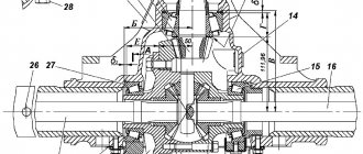
Rice. 2.4.29. Mutual arrangement of parts of the body, cover and differential of the front drive axle: 1 - axis; 2 - body; 3 - shims; 4 - cork; 5 - bearing; 6 - holder of glands; 7 - cuffs; 8, 10 - covers; 9 - worm; 11 - left differential box; 12 - driven disk; 13 - drive drive; 14 - cup; 15 - gear; 16 - satellite; 17 — axes of satellites; 18 - right differential box; 19 - driven gear; 20 - nut
If during the inspection breakage or wear of the differential parts is detected, and also if it is necessary to notice the main gear gears, they proceed to remove the differential (Fig. 2.4.30).
To disassemble the differential, unscrew the bolts tightening the boxes; it should be borne in mind that it is not recommended to dismantle and change the relative position of the differential boxes. Therefore, before disconnecting them, check the digital marking on the outer surfaces and, if necessary, restore it (Fig. 2.4.31-2.4.33).
After assembling and installing the differential in the axle housing, the axial movement of the driven gear of the final drive is checked (clearance in the differential bearings). When moving the gear in the axial direction, the indicator readings should be in the range of 0.01-0.10 mm.
Next, adjust the axial clearance in the bearings of the main gear (Fig. 2.4.34) and the differential and the main gear are installed in the axle housing. Then they check and, if necessary, adjust the side clearance between the teeth of the bevel gears (Fig. 2.4.35).
Rice. 2.4.30. Removing the main gear and differential: 1 - main gear; 2 - differential; 3 - body
Rice. 2.4.З1. The correct relative position of the differential boxes: 1 - digital marking
Rice. 2.4.32. Pressure testing of the differential bearing: 1 - bearing; 2 - driven gear; 3 - two-arm puller
Rice. 2.4.33. Crimping of the driven gear of the differential: 1 - differential box; 2 - driven gear; 3 - two-arm puller
Rice. 2.1.34. Measurement of axial clearance in the bearings of the drive gear of the final drive: 1 - drive gear; 2 - indicator
Rice. 2.4.35. Checking the side clearance between the teeth of the main gear: 1 - cardan flange; 2 - indicator; 3 - indicator stand
The side clearance is adjusted by changing the thickness of the gasket package located under the main gear bearing cup. When removing part of the gaskets, the gap between the gears decreases, when adding gaskets it increases.
During disassembly, failed parts are replaced and those surfaces that are subject to the most intense wear are monitored.
Dimensions of parts of the drive axle of the MTZ-82 tractor, mm
Outer diameter of axle shaft and vertical shaft iodine bearing 5707
Inner diameter of the body of the conical pair and the tube of the vertical shaft under the bearing 5707
| 79 | +0,020 |
| -0,010 |
The inner diameter of the gearbox housing for bearings:
The outer diameter of the drive gear of the lower bevel pair for bearings:
Wheel flange outer diameter for bearings:
The inner diameter of the cup of the bearings of the flange of the wheel disk under the bearing 7212
In the case of replacing the wheel gear bearings and its parts, as well as checking its technical condition, a number of control and adjustment works are carried out, including monitoring and adjusting the wheel flange bearings, checking the correct assembly of the upper and lower bevel gear pairs of the wheel gear (Fig. 2.4.36).
To check the technical condition of the bearings, remove the wheel flange, fix the tripod of the measuring device on the gearbox housing and rub the indicator leg into the flange. By moving the flange in the axial direction to failure, the indicator readings are determined. With indicator readings of more than 0.5 mm, tapered bearings are adjusted by changing the total thickness of the adjusting rings (Fig. 2.4.37), which are located between the inner races of the bearings, by selection or processing on a lathe. The correctness of the selection of adjusting rings without assembling the gearbox can be checked using a tool (Fig. 2.4.38).
Malfunctions and causes of failure of the FDA MTZ 82
Failure of the FDA operation is possible due to two types of reasons - a malfunction of the FDA drive or a breakdown of the front axle mechanism itself.
FDA drive problems
- Failure in the operation of the transfer case, which makes it impossible to transfer power to the intermediate drive support or disrupts the switching of the FDA operating modes. You can visually determine the breakdown if there is no rotation of the cardan shaft connecting the transfer case with the intermediate support with the forced FDA operation mode turned on and the axle final drive cardan disconnected. The reasons are: malfunction of the assembly or incorrect adjustment of the drive for switching on the FDA operating modes, wear or contamination of the transfer case mechanism.
- Malfunction or incorrect adjustment of the friction clutch of the intermediate support of the FDA drive - accompanied by overheating of the assembly and extrusion of boiled lubricant from the support housing through the seals. In this case, the transmission of torque from the support to the main gear of the FDA is disrupted or completely absent. This can usually be determined when driving under load with the axle drive engaged.
Drive transmission units to the front axle MTZ 82
Causes of PVM breakdowns
A common cause of failures in the operation of the FDA is the wear or destruction of parts of the mechanism. The main factors affecting the intensity of wear are:
- Insufficient lubrication of mechanisms due to improper control of the oil level in the axle housings, while ignoring leaks and the ingress of abrasive contaminants in broken assembly seals.
- Incorrect adjustment of the gaps in the meshing of the gear pairs and the bearing cages of the rotation supports in the mechanism;
- Excessive traction loads and weight loads on the front axle, negatively affecting the axle mechanism.
So, to prevent breakdowns, traction and sudden dynamic loads on the FDA are limited by setting the operation of the friction clutch of the intermediate drive support within 400 - 800 N.m. And also, according to the manufacturer's operational requirements, for the normal operation of the universal portal FDA, the additional load on the front axle of the MTZ 82 tractor should not exceed 800 kg.
The disadvantage of FDA MTZ 82 is a large number of interfaces with seals in the bridge structure. In connection with this feature, one of the main diseases of the assembly is a lubricant leak. As a result, the upper bevel pairs of the final drive suffer from frequent breakdowns.
Common PVM failures
Common symptoms of a bridge failure are overheating of the assembly cases, jerks during the operation of the bridge, noise and rattle in the mechanism.
Violation of the main transmission of the bridge
Accompanied by a hum in the operation of the gearbox and heating of the case above 60 ° C (checked if it is impossible to touch the hand for a long time). The reasons are the violation of the allowable clearances in the rotation bearings, the engagement of the gears of the final drive and the differential as a result of wear of the mechanism or improper adjustment. An indirect cause that affects the operation and condition of the main pair of FDA gears is the condition of the cardan shaft articulations and the total axial play of the shafts in the drive units, which creates axial runout on the FDA drive gear.
Violation of the axle differential
Accompanied by noise in operation and overheating of the case. The reasons are also the wear of the assembly parts. The absence of automatic differential lock indicates the wear of the friction discs of the blocking clutches built into the assembly body. In the absence of lubrication of the mechanism and overheating of the differential, jamming of the locking clutches is possible as a result of soldering of the discs.
Break in the transmission of torque from the semi-axes of the tractor to the vertical shafts of final drives
The causes of the problem are the painting of the teeth of the bevel upper pair of final drive gears, jamming of the bearings of the vertical shaft as a result of insufficient lubrication, wear of the splines in the lower part of the vertical shaft or its destruction. The breakage of the vertical shaft indicates unacceptable wear in the pivoting pivot pair - the sleeve and the pivot pipe. The transmission of rotation from the axle shafts to the side parts is checked, observing through the open hatch of the upper conical pair, during the rotation of the shank of the drive gear of the main axle drive.
Jamming of the kingpin in the final drive of the FDA
Accompanied by the impossibility of turning the steered wheels. The reasons are insufficient lubrication of the pair "pivot sleeve - pivot pipe", as well as unacceptable wear of the pair and breakage of the pivot pipe flange.
Violation of the work of the lower conical pair in the final drive
Occurs when the bearings are worn and the gaps in the cages increase on the axis of rotation of the flange for fastening the wheel, where the axial play provokes a beating in the gear pair of gears, disrupting the normal engagement.
Repair
Promoport repair should be carried out according to the manufacturer's instructions. It is also convenient to use the repair video - there are a lot of videos on the Internet showing the process of parsing and adjusting the support in detail.
Be sure to read: Tractor T 40
It is very important to follow the manufacturer's recommendations. Some masters, especially those with extensive experience, make changes to the components and assemblies. In some cases, such intervention is justified, but more often the “improvement” of the design of the part entails overloading larger units. A common example is when all the “extra” filling is removed from the support, after which it really breaks less often, but then the entire front axle fails due to overloads.
The cardan drive is supplied by the manufacturer in dynamic balancing, which can be disturbed over time. It should not be disassembled unless absolutely necessary. After repair, the shaft assembly must be re-balanced by welding metal plates on both ends of the pipe. The imbalance should be within 55 g per cm.
FDA disassembly procedure MTZ 82
Considering the design features of the assembly, and the presence of a number of pressed-on mates in parts, it is recommended to have screw pullers in the arsenal of devices for disassembly. The screw tool will provide a comfortable disconnection without damaging the parts.
Pinion Assembly Part Locations
Dismantling the main gear of the bridge
The dismantling of the main gear cup is carried out by unscrewing the fixing bolts of the cup flange with the cardan shaft disconnected. The body 4 of the drive gear is pressed out by screwing two mounting bolts into the special holes of the cup flange.
To replace the cuff 6 in the cup of the drive gear, unscrew the splinted adjusting nut 9 at the end of the shaft 1 and remove the connecting flange 8 of the cardan from the splines. Next, a single shaft with a gear is removed and a complete disassembly is carried out.
Removing the housing cover of the FDA (old model) MTZ
Access to axle final drive and differential
Pressing out differential bearing
Pressing out the driven gear of the final drive
Correct mutual placement of differential half-cases
The dismantling of the differential with the driven gear of the main gear is carried out by disconnecting the connecting flanges of the main gear housing and the axle shaft covers or the axle cover. The bearings of the differential and the driven gear of the final drive are pressed out from the housing of the assembly using a screw puller with grippers.
Location of FDA main gearbox parts
Detachment onboard
To disconnect the final drive assembly from the side housing of the axle shaft, it is necessary to jack up the repaired side of the axle, unscrew the bolts securing the flanges of the pivot pipe cups and the sleeve from the housing of the upper bevel gear. With the help of dismantling bolts screwed into the flange holes, press the king pin from the sleeve in the wheel gear housing.
Disassembly of the wheel reducer
To disconnect the gears of the lower pair of final drive, unscrew the bolts around the perimeter of the wheel gear cover, after placing a container under the gear to collect oil. In the connection of the housing cover flanges, in case of repair of later versions of the MTZ 82 FDA, dismantle the adjusting shims of the gear engagement.
Final drive detail
To carry out an audit of the bearing part of the wheel flange, the bolts in the end of the flange shaft are released from the fixing folding plate, two fixing bolts are unscrewed, the bearing with the separator and the inner race is removed, then the driven gear is removed from the splines of the flange shaft, the part is knocked out with a blow of a wooden spacer into the end of the shaft. bearings and adjusting rings.
Removing the wheel gear cover
Dismantling the stuffing box housing from the wheel gear cover
Dismantling the driven gear of the wheel reducer
Pressing out the bearing cup from the wheel gear cover
Mounting bolts are also screwed into the flanges of the parts to press off the stuffing box or the cup of the bearing part.
Dismantling the axle shaft and vertical shaft
To remove the axle shaft with gear and bearings, you need to unscrew the lock screw from the body of the upper conical pair. To remove the vertical shaft, unscrew the two corkscrews in the upper part of the pivot pipe, which rest against the bearing cage. Bearings and inner races from the shaft and axle shaft are pressed with a puller.
Detachment of final drive
Pressing the shaft out of the housing
Pressing out the drive gear of the wheel reducer
Dismantling the bearings of the drive gear of the wheel reducer
Extraction of bearings from the axle shaft
Dismantling the axle shaft housing
Unscrew the fixing nuts of the locking pins on the screw gauge adjustment mechanism. Pressing out the axle housing from the axle cover or axle housing is carried out with a puller.
Releasing the locking wedges of the axle housing
Vypressovka of the case of a semiaxis assy
The device and scheme of the front axle MTZ-82
We will study this mechanism completely, but first you need to fully understand the scheme and devices of this mechanism. To do this, we present its complete scheme and give a decoding of the details.
The main task of the front axle of the Belarus MTZ-82 tractor is to transfer torque from the engine to the guide front wheels. The mechanism itself consists of: transmission, front differential and wheel gear.
The transmission design is made up of two bevel gears with helical teeth. The drive gear (37) is placed on a tapered roller bearing (40) in the cup (39). The driven (25) is seated in the belt of the differential housing (27) and splines, with the help of a nut (24) it is fixed from any axial movements.
Front drive axle differential
This mechanism uses a self-locking limited slip differential. The cover (31) and the housing (27) are connected by bolts, they contain semi-axial gears (21), satellite (30, friction discs driven (36) and driving (28). As well as pressure cups (35).
The differential integrally fixes the two axle shafts, and also eliminates separate wheel slip and significantly increases the tractive force of the tractor. When it is turned on, the wheels lock. The reinforcement from the axles passes to the satellites, which are transmitted by the shoulder cups (35). This, in turn, compresses the friction discs (26 and 36).
The differential lock is carried out with the help of friction force.
If the friction force in the discs (26 and 28) exceeds the standard deviation at the moment of rotation, then slip occurs. The MTZ-82 front axle differential is placed in the cover (20) and housing (34) on tapered roller bearings (32).
Additionally, a breather (33) is installed in the system, which maintains normal pressure in the differential cavity.
How the front axle of the tractor is connected
With the help of hollow axles (58) and a beam, the bridge is connected, in turn, the hollow axles ensure the rolling of the front wheels and the axle in the transverse plane. Stopping of the axes from movement occurs with the help of straps (59).
In the sleeves of the cover (20) and the one-piece body (34), mechanical final drive gearboxes are placed. They consist of pairs of bevel gears that serve as hinges of equal angular velocities.
Splined shanks with gears secure the axle shaft and the vertical shaft of the differential. The tractor axle shaft itself is mounted on two roller-type tapered bearings (14), and the vertical shaft rests on them and its installation takes place in the bore of the kingpin pipe (13). The cuffs (16 and 45) together with the paronite gasket seal the cavity (19) cover surface.
The kingpin tube (13) is supported by a coil spring (49). The pipe itself enters the sleeve (47), it is also pressed into the gear housing (53) and locked with a pin.
How torque is transmitted
The process itself is quite simple to understand, first the disk flange (2) rotates on a roller-type bearing (50) and a pair of conical ones (4), which are pressed into a glass (6), which is located in the bore of the cover (1).
FDA main gearbox adjustment
Since the main pair of gears operates under conditions of significant axial loads, it is recommended to install bearings without clearance with a preload in cages of 0.02 - 0.05 mm. This setting provides stable meshing in the gears and allows you to delay the appearance of gaps as a result of the development of parts. Bearings, with this setting, work due to the elasticity of the metal in the cages.
Adjusting the axial clearance in the pinion bearings
The clearance in the drive gear bearings is eliminated by tightening the nut on the threaded end of the shaft. The appearance of an axial clearance provokes beating and subsequent destruction of the stuffing box. If, after maximum tightening, there is still an axial clearance, then the thickness of the adjusting bushings is reduced by grinding the drive gear bearings installed between the races. Reducing the size of the bushings by +0.05 mm play will allow tightening the shank nut and eliminating the play in the clamps with an interference fit. The size of the backlash is determined by an indicator attached to the glass and the gear itself. The tightening is carried out while turning the shaft so that the bearing rollers take their place in the cages. A slight heating of the drive gear housing is allowed after the backlash is eliminated, not higher than 60 ° C.
Checking the axial clearance in the bearings of the main drive gear of the FDA
Differential bearing clearance adjustment
The check is carried out with the stop of the mount in the body of the bridge and the end part of the driven gear. Diagnosis is carried out every 3000 hours, after checking the tightening of the connecting flanges of the axle housing and axle housings. If play is detected, the number of shims between the connecting flanges of the housing and the axle cover (axle housing) is reduced by the size of the play or more by 0.05 mm from the diagnosed gap. In correctly adjusted bearings, the interference should be within 0.01 - 0.1 mm.
Lateral engagement clearance of the main pair
It should be noted right away that the adjustment of the engagement of the main pair is carried out only initially when it is completely replaced or the bearings of the axle housing, differential housings, and bearings in the pinion cup are replaced. Adjustment of worn gears is prohibited, since such an adjustment will disrupt the organic engagement of the gears, shift the contact patch of the teeth and lead to rapid wear or jamming of the pair. It is also forbidden to install dismantled pairs or replace individual gears in a pair, that is, the replacement is carried out strictly in pairs in the manufacturer's kit. Reconfiguration is carried out in case of diagnosing the side clearance in the engagement above 1.2-1.5 mm of the new main pair, which is the result of incorrect assembly.
Checking the clearance in the meshing of the final drive gears
The clearance in the engagement of the gears of the main pair is adjusted only if there are no axial clearances in the bearings of the drive gear and differential bearings. Adjustment is carried out by installing shims. The position of the drive gear is regulated by gaskets installed under the flange of the glass together with fastenings to the axle body. The driven gear is set using the selection of gaskets between the differential case and the end face of the driven gear, which is seated on splines.
Adjusting the contact of the teeth of the main gear pair
After the adjustment is made, the contact patch in the meshing of the teeth is checked. Correct setting shows that the entire length of the tooth is involved in the engagement. To check, several gear teeth are painted with a thin layer of paint, a pinion cup is installed and the gear teeth are rolled several times in both directions. After that, the glass with the drive gear is pressed out and the contact patch is inspected.
The correct spot should be located closer to the narrow end of the tooth, occupying an area of at least 50% along the length and width of the tooth (Figure a ). If the contact patch does not match, adjustments must be made.
- If the spot is located on the top of the tooth, you need to bring the drive gear closer to the driven gear by reducing the number of gaskets between the cup flange and the bridge body (option b ).
- If the spot is located too low at the base of the tooth, the number of spacers between the glass and the body is increased, thus moving the drive gear away from the driven gear (option c ).
- If the stain is shifted closer to the narrow edge of the tooth, you need to move the driven gear away from the drive gear, reducing the thickness of the gasket package between the differential housing and the driven gear ( r ).
- With a displaced spot closer to the wide edge of the tooth, it is necessary to bring the driven gear closer to the leading one, increasing the thickness of the gasket package ( e ).
gear tooth contact options
Repair and adjustment of final drives
During operation, the mechanisms of the FDA final drive reduction gear are not adjusted. The complete adjustment of the clearances in the bearings and the engagement of the gear pairs is carried out in the process of assembling the assembly during the repair.
Setting the clearance in the rotation bearings of the upper conical pair
The axial clearance in the axle bearings on the upper part is adjusted by tightening the clamping nut. Initially, the nut is tightened to a state of tight rotation of the bearing races. When tightening, turn the outer clips so that the rollers take their correct place. After that, the nut is released exactly enough so that the bearing races begin to rotate freely and the clearance in the bearing does not exceed 0.1 mm. Although the new adjustment recommendations indicate that the bearings are installed with a preload in the range of 0.05-0.15 mm. This requirement exists and has the advantage of extended service life before unacceptable backlash occurs in the bearings. After adjusting the hook, it is fixed by punching.
Checking the axial clearance of vertical shaft bearings
An important point in setting is the strict position of the spacer ring between the outer races of a pair of bearings, without protruding beyond the outer edges. Otherwise, the protruding ring will prevent the shaft from being pressed into the seat.
Adjusting the engagement of the upper bevel gear pair
Adjustment of the side clearance in the meshing of the upper pair is carried out only by shifting the position of the vertical shaft with the help of split gaskets 3 installed between the flange of the gear pair housing and the pivot pipe cup. The axle position does not change. Normal side clearance should be within 0.1-0.55 mm.
Installing the plate pack when adjusting the engagement of the upper conical pair
Checking the engagement setting is checked by first removing the grease from the pair housing and locking the vertical shaft. A lead plate is installed between the teeth of the gears, the axle shaft is rotated from the flange of the cardan of the final drive. The depth of the dents will show the actual engagement clearance. After setting the gap, check the contact patch in the engagement.
When installing the horizontal and vertical shafts in the seats, it is important to ensure that the locking pins holding the shafts in the seats do not touch the bearing cages.
Wheel bearing adjustment
Old reference books indicate an installation clearance in the tapered bearings of the wheel flange of 0.2 mm, later operating instructions indicate that the bearings are adjusted with an interference of 0.1 mm. Adjustment is carried out by selecting the width of the rings installed between the inner bearing races on the flange shaft. With the correct adjustment of the bearings, the service life before the appearance of gaps up to 0.4 mm can be up to 5000-6000 hours. Therefore, the adjustment is made during the repair of the wheel gear. If the backlash appeared prematurely, it is necessary to revise the gearbox and eliminate the backlash.
Installation of adjusting rings of tapered bearings of the wheel reducer
Checking the axial clearance in the tapered bearings of the wheel flange with an indicator
The operation is carried out in the following order:
- Remove the wheel from the mounting flange, drain the grease from the gearbox, disconnect the cover from the gearbox housing and dismantle it together with the wheel drive driven gear and the flanged shaft with the bearing assembly.
- Initially, you need to try to eliminate the backlash by tightening the mounting bolts on the end of the shaft. If the tightening does not work, then the bearing assembly is completely disassembled and the width of the spacer rings is reduced by grinding by the amount of play.
- After that, the bearing assembly is assembled and the fixing end bolts on the shaft are tightened. When assembling, it is important to check that the ends of the rings between the bearings are strictly in contact with the inner races and do not rest against the separators.
- After checking the set clearance, the fixing bolts are fixed with a folding plate.
When diagnosing the bearing part of the wheel reducer, it must be borne in mind that in the configuration of the wheel reducer manufacturer's factory, the width of one adjusting ring between the bearings is 7 mm each, and the sum of the two rings is 14 mm. The overall smaller width of the rings indicates the previously made adjustment of the bearings and their incomplete resource.
Adjustment of engagement of gears of the lower bevel pair
The adjustment is carried out by moving the driven gear with the help of split adjusting plates installed in a package between the cover of the gearbox housing and the flange of the bearing assembly cup or, in more modern versions of the assembly, between the cover and the gearbox housing. The side clearance of a new pair of gears is set within 0.26-0.65 mm. This value corresponds to the angular displacement of the wheel mounting flange at the bolt mounting radius. To check the clearance, the drive gear of the lower pair is locked.
Adjustment of the clearance in the engagement of the lower conical pair of the final drive
Checking the clearance in the engagement of the upper and lower conical pairs with an indicator
Replacement of the sleeve and the pivot pipe onboard
With sufficient development of the kingpin and sleeve, a beating occurs that affects the state of the entire mechanism of the final drive. When repairing, these factors must be taken into account and it is advisable to replace the parts of the rotary mechanism in pairs, and not in choosing one part, assessing the wear of each. According to the manufacturer's recommendations, a play of more than 1 mm between the parts of the rotary pair is not acceptable and must be replaced.
Pressing the sleeve out of the onboard body
Particular difficulties arise when pressing the sleeve out of the gearbox housing. Often, as a result of jamming of this pair of parts of the onboard gearbox swivel mechanism, without the use of certain technologies, it is almost impossible to perform an operation while maintaining the integrity of the parts.
A screw puller is used to press out the worn sleeve from the gearbox housing. First, you need to remove the pin fixing the sleeve installed in the body of the housing from the inside. Taking into account that the sleeve will be replaced with a new one during dismantling, to remove it, four symmetrically located longitudinal seams are welded along the inner contact surface with the pivot. The internal stresses of the metal, created by welded seams, will loosen the fit of the sleeve in the body. After that, they begin to extrude the part using a screw puller. During assembly, to facilitate installation, the sleeve is seated in the gearbox housing preheated by the burner.
One of the sore points of the final drive is the upper part in the junction of the sleeve with the pivot pipe, which suffers from insufficient lubrication and abrasive dust entering through broken seals. To improve the working conditions of the pivot pair, an oiler is installed in the upper part of the body, which allows several strokes of the syringe to deliver lubricant between the contact surfaces of the sleeve and the pivot pipe. Such modernization allows to significantly increase the working life of the onboard gearbox.
Oil leak repair
Every experienced tractor driver is familiar with the unfortunate bewilderment that he experienced when he discovered completely dry cavities of the upper bevel pairs of the final drive. The oil at the same time went into the cavity of the wheel gear despite the recent repair of the bridge and the replacement of seals and seals of the upper conical pair. This was discovered when opening the control-filler plug on the wheel gear housing, where excess oil immediately splashed out.
Leak factor
In addition to the failure of the seals, in the design of the unit, one of the reasons for the constant leakage of lubricant from the cavities of the final drives is the heating of the oil and the appearance of excess pressure in the cavity of the mechanism during the active operation of the gear pairs. As a result, the lubricant is squeezed out through the seals and the mechanism is subjected to dry operation.
Solutions
To relieve excess pressure from the working cavity, breathers are installed in the housing or cover of the gearbox instead of filler plugs. So, it was noted by practitioners that when a breather is installed in the housing cover of the upper conical pair, the flow of oil down into the wheel gear stops and the lubricant does not leave the upper cavity. Naturally, the effect of the breathers will be only with the integrity of all seals.
Also, according to the experience of tractor operators, it is possible to significantly reduce leakage from the housings of the upper pairs of tapered bearings by creating a plug of grease in the cavity of the pivot pipe. During repair, the cavity is clogged with grease, which prevents oil from draining from the cavity of the upper conical pair to the bottom of the gearbox.
